Serial parallel structure electric power transformation device

A power conversion device and power converter technology, which are applied in the direction of converting irreversible DC power input into AC power output, emergency protection circuit devices, electrical components, etc. and other problems to achieve the effect of suppressing misoperation and quick disconnection

Active Publication Date: 2009-05-06
HITACHI LTD
View PDF2 Cites 5 Cited by
  • Summary
  • Abstract
  • Description
  • Claims
  • Application Information

AI Technical Summary

Problems solved by technology

Here, when computing processing devices such as microcomputers mounted on the control board are directly connected, although high-speed transmission is possible, there is a possibility that the computing processing devices themselves may malfunction due to influences such as electromagnetic disturbances.
In addition, if the adverse effects of electromagnetic barriers are to be prevented, other adverse effects may occur such as longer time for the disconnection operation

Method used


Image

  • Serial parallel structure electric power transformation device
  • Serial parallel structure electric power transformation device
  • Serial parallel structure electric power transformation device

Examples


no. 1 example

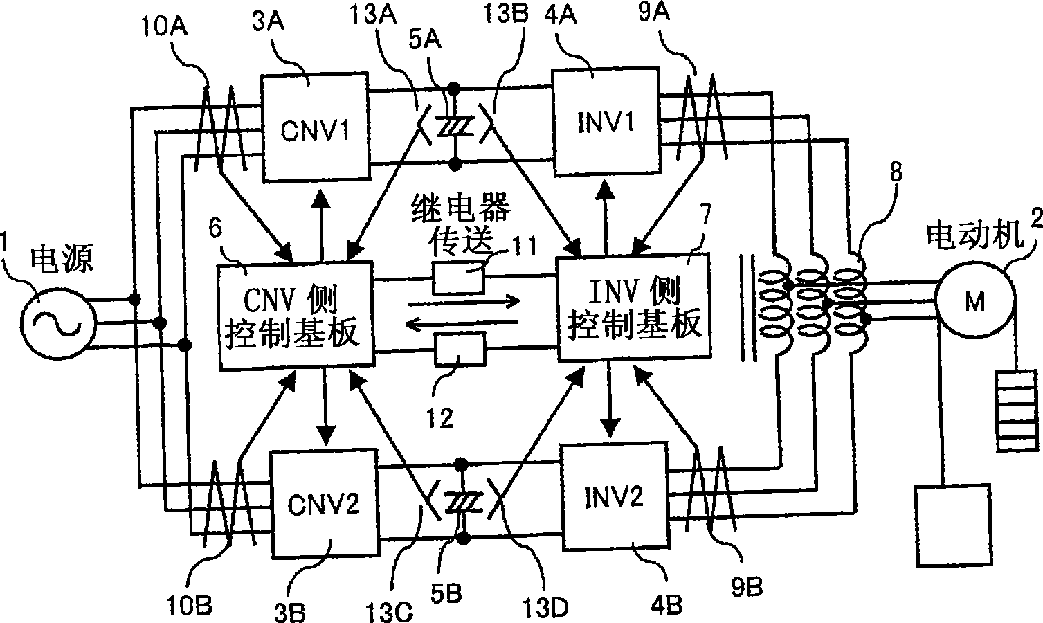
[0044] figure 1 Indicates a power conversion device, which is composed of the following parts: a commercial power supply 1; a motor 2; a first system PWM rectifier 3A; a second system PWM rectifier 3B; a first system inverter 4A; a second system inverter 4B ; 1st system smoothing capacitor 5A; 2nd system smoothing capacitor 5B; PWM rectifier side control substrate 6; inverter side control substrate 7; output side reactor 8; 1st system inverter side current detector 9A; System inverter side current detector 9B; first system PWM rectifier side current detector 10A; second system PWM rectifier side current detector 10B; signal transmission from PWM rectifier side control board 6 to inverter side control board 7 The relay 11 used when the signal is transmitted from the inverter side control substrate 7 to the PWM rectifier side control substrate 6. The relay 12 used when detecting the voltage of the smoothing capacitor and transmitting the voltage information to the control substr...


PUM


Abstract

The present invention provides a set of power convertor which is in a parallel structure, which can execute high-speed switching-off action when the direct-current and zero-phase current of power transformer are abnormal, and furthermore the effect by electromagnetic obstacle, etc. is few. The action of power convertor is stable. The set of parallel power convertor is obtained through parallel connecting the power transformers, wherein each of the transformers is provided with a PWM rectifier (3) and an inverter (4). Furthermore the set of power convertor is provided with a PWM rectifier side calculation processing device which executes control calculation of PWM rectifier (3), and an inverter side calculation processing device which executes the control calculation of inverter (4), wherein, the PWM rectifier (3) and inverter (4) are driven by a control calculation device which is installed on single control substrates (6, 7). When a control calculation device detects the abnormity of power convertor, an abnormity detection signal is transmitted to the other control calculation device through a relay (11) or an optical coupler.

Description

technical field [0001] The present invention relates to a power conversion device with a parallel structure in which two power converters are connected in parallel for the purpose of increasing the capacity. Background technique [0002] As a known technology, for example, in the elevator speed control device described in Patent Document 1, the power conversion device is connected in parallel to realize a large capacity. In this power conversion device, the output of the current detector and the To find the zero-phase current, reduce the zero-phase current by controlling the output of the inverter. [0003] In addition, in the power conversion device described in Patent Document 2, the capacity of the power conversion devices is increased by connecting them in parallel. In this power conversion device, a smoothing circuit is independently configured to constitute an inverter of a plurality of sets of power conversion circuits. At least one control circuit in the circuit and...

Claims


Application Information

Patent Timeline
IPC IPC(8): H02M7/48H02H7/10
Inventor 保立尚史岸川孝生大沼直人迫田友治蛭田清玄三田史明稻叶博美绫野秀树森和久
Owner HITACHI LTD
Why Eureka
Try Eureka