Method of providing consistent quality of target material removal by lasers having different output performance characteristics

一种激光器、质量的技术,应用在激光器、激光器零部件、声子激发器等方向

Inactive Publication Date: 2009-05-06
ELECTRO SCI IND INC
View PDF0 Cites 10 Cited by
  • Summary
  • Abstract
  • Description
  • Claims
  • Application Information

AI Technical Summary

Problems solved by technology

[0007] The invention realizes the adjustment of laser pulse energy, thereby solving the influence caused by the change of laser pulse width in different lasers

Method used


Image

  • Method of providing consistent quality of target material removal by lasers having different output performance characteristics
  • Method of providing consistent quality of target material removal by lasers having different output performance characteristics
  • Method of providing consistent quality of target material removal by lasers having different output performance characteristics

Examples


Embodiment Construction

[0014] Preferred embodiments of the present invention require the use of solid-state UV lasers to perform drilling and ablation of circuit materials such as uniform films with or without metal cladding, particle-filled resins, polyimides, and fiber-reinforced polymers. The Model ABF circuit board dielectric material manufactured by Ajinomoto Fine-Techno Co., Inc. of Kawasaki, Japan is the target material, and the following description is based on this target material. The following description is directed to drilling, but the invention is also applicable to other methods of material removal, such as joint severing, material trimming, annealing, and scribing.

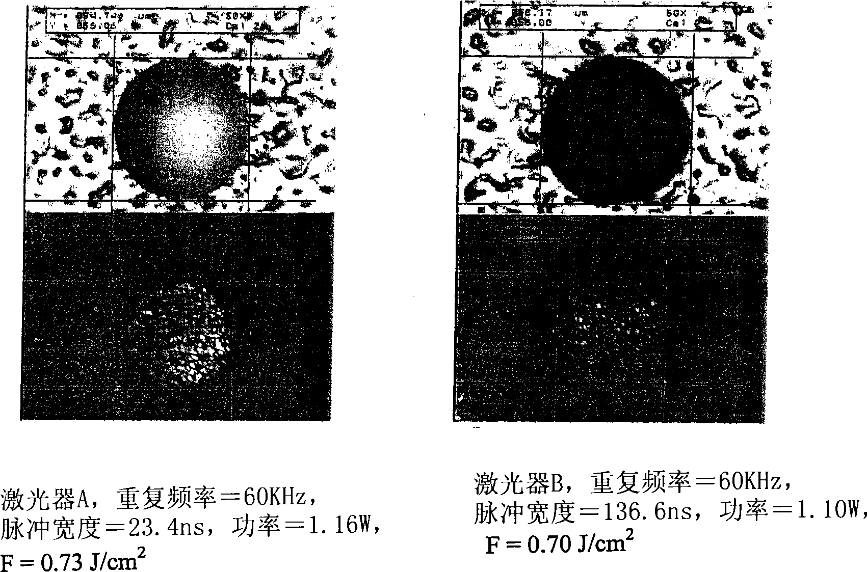
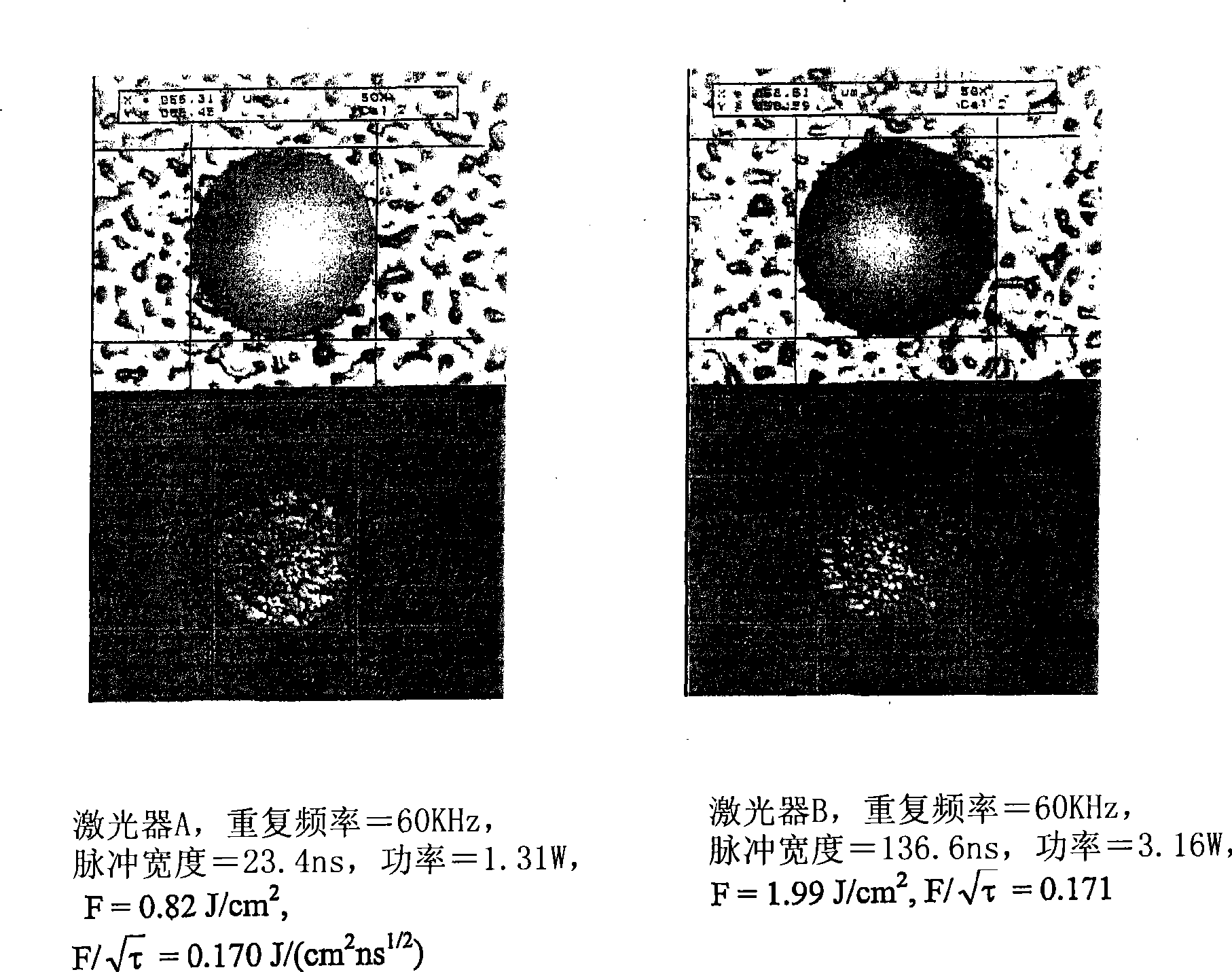
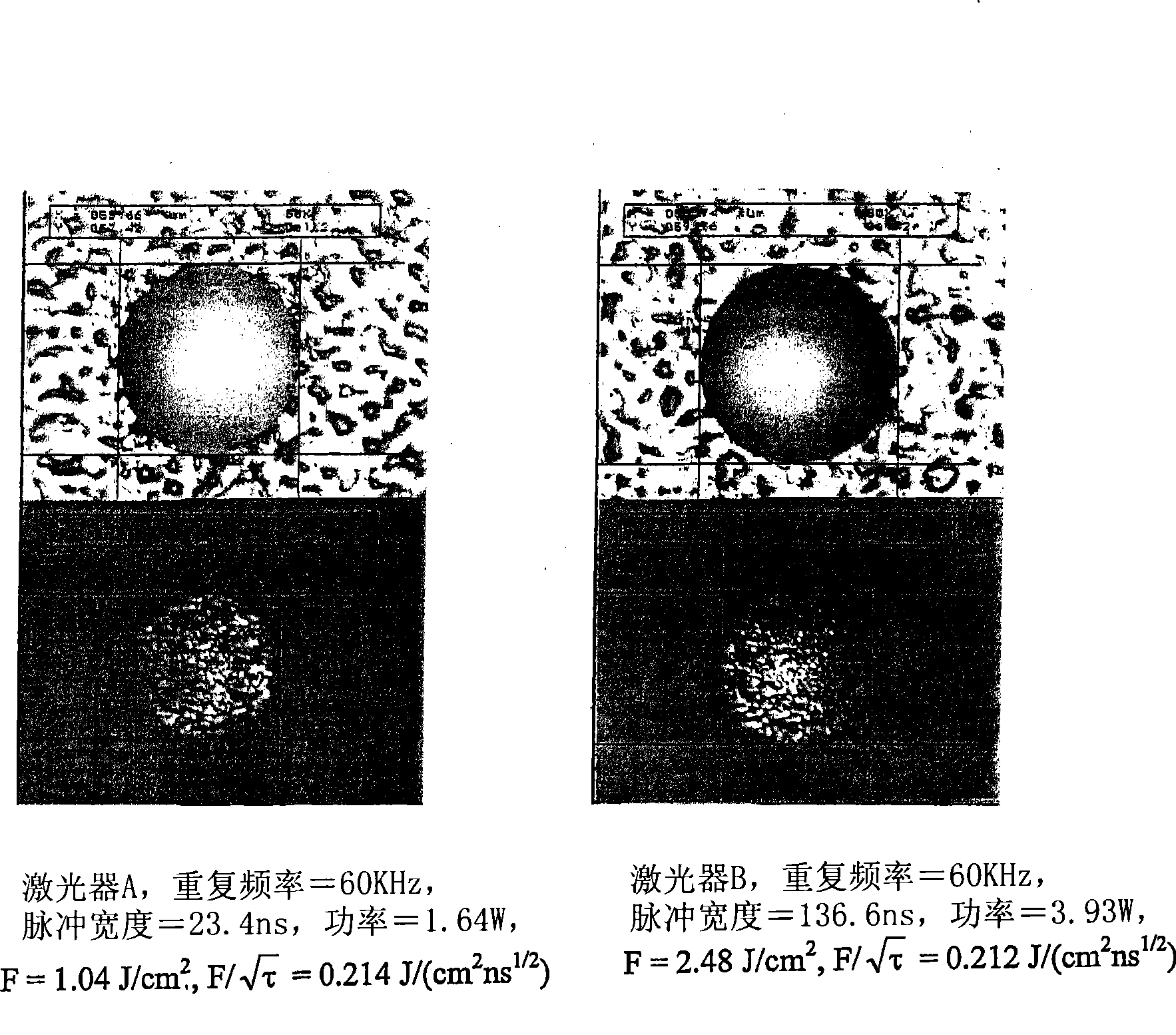
[0015] figure 1 is a set of four photomicrographs showing the problem solved by the present invention. figure 1 Light micrographs are shown of two 58 micron diameter drilled holes drilled to a depth of 35 microns to 40 microns with approximately the same fluence level using a 355 nm UV laser with different pulse widths....


PUM


Abstract

Laser pulse energy adjustments are motivated by an understanding of the effect of laser pulse width variations among different lasers on satisfying a quality metric associated with a laser-processed target. In a preferred embodiment, the adjustments normalize this effect among different lasers drilling vias in a target specimen. The number of pulses delivered to the target specimen to form each via can be modified, based on the pulse energy applied to the via location, to control different via quality metrics.

Description

technical field [0001] The present invention relates to the use of lasers to drill holes or process parts in materials for electronic material products, and in particular to techniques for producing consistently high quality drilled holes after material processing by laser-based systems having varying operating output parameters or area. Background technique [0002] Lasers are used to drill holes and ablate in materials for electronic materials products such as homogeneous thin films with or without metal cladding, particle-filled resins, polyimides, and fiber-reinforced polymers. The state of the art in solid state UV laser drilling is, for example, setting and controlling or monitoring the laser pulse energy by setting and controlling the laser pulse power and repetition rate for the desired process. Gaussian beam optics and imaging beam optics configurations are used in this manner. Other laser output performance characteristics vary across lasers, but remain within la...

Claims


Application Information

Patent Timeline
Patent Type & Authority Applications(China)
IPC IPC(8): H01S3/10B23K26/06B23K26/38H05K3/00
CPCH05K2203/163H05K3/0032B23K2203/12B23K26/381B23K26/063B23K2201/36B23K26/401B23K26/4085B23K26/4095B23K26/4065B23K26/40B23K26/0622B23K26/382B23K2101/34B23K2101/35B23K2101/36B23K2103/16B23K2103/42B23K2103/50H01S3/10
Inventor W·莱G·西盟森J·豪尔顿M·恩瑞
Owner ELECTRO SCI IND INC
Why Eureka
Try Eureka