Mobile riding wheel frame

A movable type and turbine technology, which is applied in the manufacture of converters, etc., can solve the problems of loose support rollers and cannot solve the problems of maintenance and replacement in high temperature environments, and achieve the effects of avoiding replacement, shortening the replacement and maintenance cycle, and improving safety and operability

Inactive Publication Date: 2010-05-26
SHANGHAI BAOSTEEL MAGNETICS
View PDF5 Cites 0 Cited by
  • Summary
  • Abstract
  • Description
  • Claims
  • Application Information

AI Technical Summary

Problems solved by technology

Patent No. 91225958.2 "Centrifuge Supporting Wheel Device" has the effect of "basically eliminating the loosening of the base and the overall bearing in the past, bearing damage, drive shaft breakage, and loosening of the supporting wheel", which cannot solve the problem of maintenance and replacement in high temperature environments

Method used


Image

  • Mobile riding wheel frame
  • Mobile riding wheel frame
  • Mobile riding wheel frame

Examples


Embodiment 1

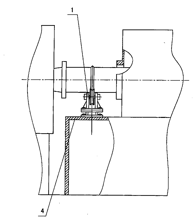
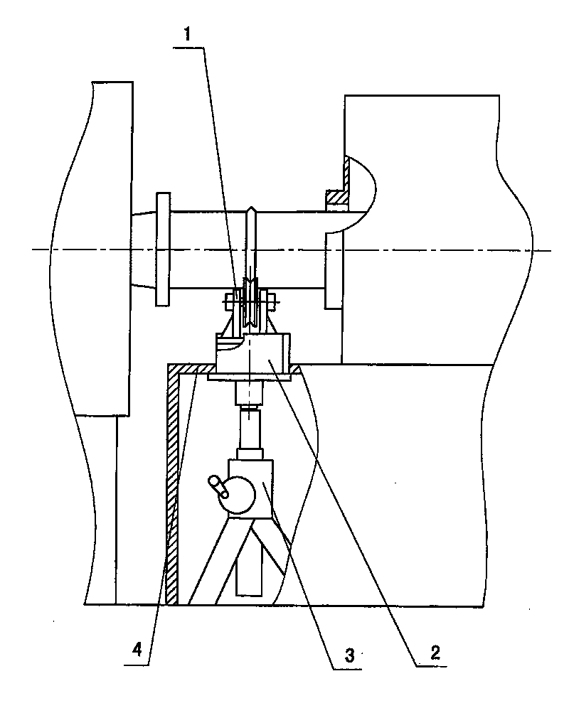
[0045] A rectangular lifting hole is set on the table top 4 of the steel plate stand, and a jack lifting support mechanism 3 is set below the lifting hole inside the steel plate stand, and the jack supports the movable connecting frame 2, and the movable connecting frame 2 buckles Supporting wheel 1.

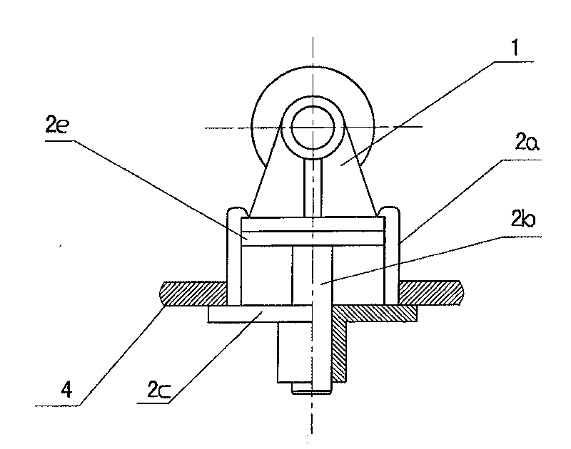
[0046] The movable connection frame 2 includes a supporting plate 2c, a push rod 2b, a top plate 2e and a limiting plate 2a;

[0047] The size of the supporting plate 2c is larger than the opening of the lifting hole, and a sliding hole is provided in the center of the supporting plate 2c, and the sliding hole is a circular tube with a length;

[0048] Two limit plates 2a are vertically fixed on both sides of the supporting plate 2c, the distance between the two limit plates 2a is equal to the width of the base of the supporting wheel 1, and there is a gap that can move mutually; the upper end of the limit plate 2a is The size of the rectangle formed on the outside of the two l...

Embodiment 2

[0054] Same as Embodiment 1, only wherein the lifting support mechanism 3 is a lever mechanism, that is, one end of the lever is against the lower edge of the push rod 2b of the movable connection frame 2, the fulcrum of the lever is erected on the ground, and the other end of the lever is pressed down. Lock in the form of a buckle, firmly press one end of the lever against the lower edge of the top rod 2b of the movable connection frame 2, lift the supporting wheel 1, and firmly press and lock the base of the supporting wheel 1 between the top plate 2e and the stop , The supporting roller 1 also supports the high-temperature heating furnace tube, and the operation of this mechanism is simple and easy. In order to ensure positional accuracy, a fine-tuning screw can be provided on the hasp.

Embodiment 3

[0056] Such as Figure 5 , 6 As shown, on the basis of Embodiment 1, a flange is protruded from the upper surface of the top plate 2e to form a flange top plate 2e-2, and a sleeve-type step sleeve 2f is set between the two limiting plates 2a, and the flange The peripheral diameter of the top plate 2e-2 is smaller than the inner diameter of the step sleeve 2f, and a flange hole with the same flange position as the flange top plate 2e-2 and a corresponding diameter is opened at the bottom of the supporting wheel 1 base. When the lifting support mechanism 3 rises, it pushes the push rod 2b to move upwards, and the flange top plate 2e-2 pushes the base of the supporting roller 1 to rise to achieve the purpose of support. Simultaneously, because the flange on the upper surface of the flange top plate 2e-2 is embedded in the flange hole of the base of the supporting wheel 1, the base of the supporting wheel 1 is limited by the flange on the upper surface of the flange top plate 2e-...


PUM


Abstract

The invention relates to a structure of a supporting roller stander for replacing a supporting roller of a high-temperature converter in the metallurgical industry. The movable supporting roller stander comprises a supporting roller (1) and a steel plate platform for mounting the supporting roller (1). The structure is characterized in that a platform board (4) of the steel plate platform is provided with a lifting hole; the inside of the steel plate platform and the lower part of the lifting hole are provided with a lifting and supporting mechanism (3); the lifting and supporting mechanism (3) supports a movable connecting rack (2); and a base of the supporting roller (1) is compacted and connected between parts of the lifting and supporting mechanism (3) and the movable connecting rack (2). The structure is simple, can adopt a universal standard piece for the lifting and supporting mechanism, has low manufacturing cost, easy mounting and convenient use, avoids replacement and operation by a maintenance worker in high-temperature environment, enlarges and improves the operating environment and improves safety; and the structure does not need natural cooling or repeated heating tocause great waste to electrical energy and heat energy in replacement, avoids carrying out useless consumption on the operating time of equipment and greatly improves the working efficiency of the equipment.

Description

(1) Technical field [0001] The invention is an auxiliary device for production equipment in the metallurgical industry, in particular to a supporting wheel frame structure for replacing the supporting wheel of a high-temperature converter. (2) Background technology [0002] It is known that in the pre-burning furnace for magnetic materials in the metallurgical industry, in the tube chamber furnace of a double-tube rotary furnace composed of two parallel large-diameter metal tubes, various granular raw materials are loaded from one side of the feed port for side heating While rotating and stirring, after a certain period of operation, the finished material is discharged from the outlet on the other side. [0003] Two high-temperature furnace tubes arranged in parallel penetrate into a rectangular heating furnace, and pass through the circular tube openings at both ends. The weight does not affect its rotation driven by the sprocket. The disc supporting wheels are arranged i...

Claims


Application Information

Patent Timeline
Patent Type & Authority Patents(China)
IPC IPC(8): C21C5/46
Inventor 陈卫锋徐辉宇刘栋华刘国平顾燮峰钱爱敏
Owner SHANGHAI BAOSTEEL MAGNETICS
Why Eureka
Try Eureka