Sealing method and device for anode rod of aluminum cell

A technology for anode guide rods and sealing devices, which is applied in the field of aluminum electrolytic cell anodes, and can solve problems such as difficult to obtain sealing effects, inconspicuous effects, high temperature deformation, etc.

Inactive Publication Date: 2009-05-13
NORTHEASTERN UNIV ENG & RES INST CO LTD
View PDF0 Cites 1 Cited by
  • Summary
  • Abstract
  • Description
  • Claims
  • Application Information

AI Technical Summary

Problems solved by technology

For this reason, technicians in the aluminum electrolysis industry have proposed different methods to solve the sealing problem between the anode guide rod and the horizontal cover plate. They use a completely fixed structure to seal the anode guide rod and the horizontal cover plate. The gap between the cover panels, but its effect is not obvious
Its structure is either worn out or deformed at high temperature, and its function will gradually be lost over time.
It seems that it is difficult to obtain a very satisfactory sealing effect by purely mechanical means.

Method used


Image

  • Sealing method and device for anode rod of aluminum cell
  • Sealing method and device for anode rod of aluminum cell
  • Sealing method and device for anode rod of aluminum cell

Examples


Embodiment 1

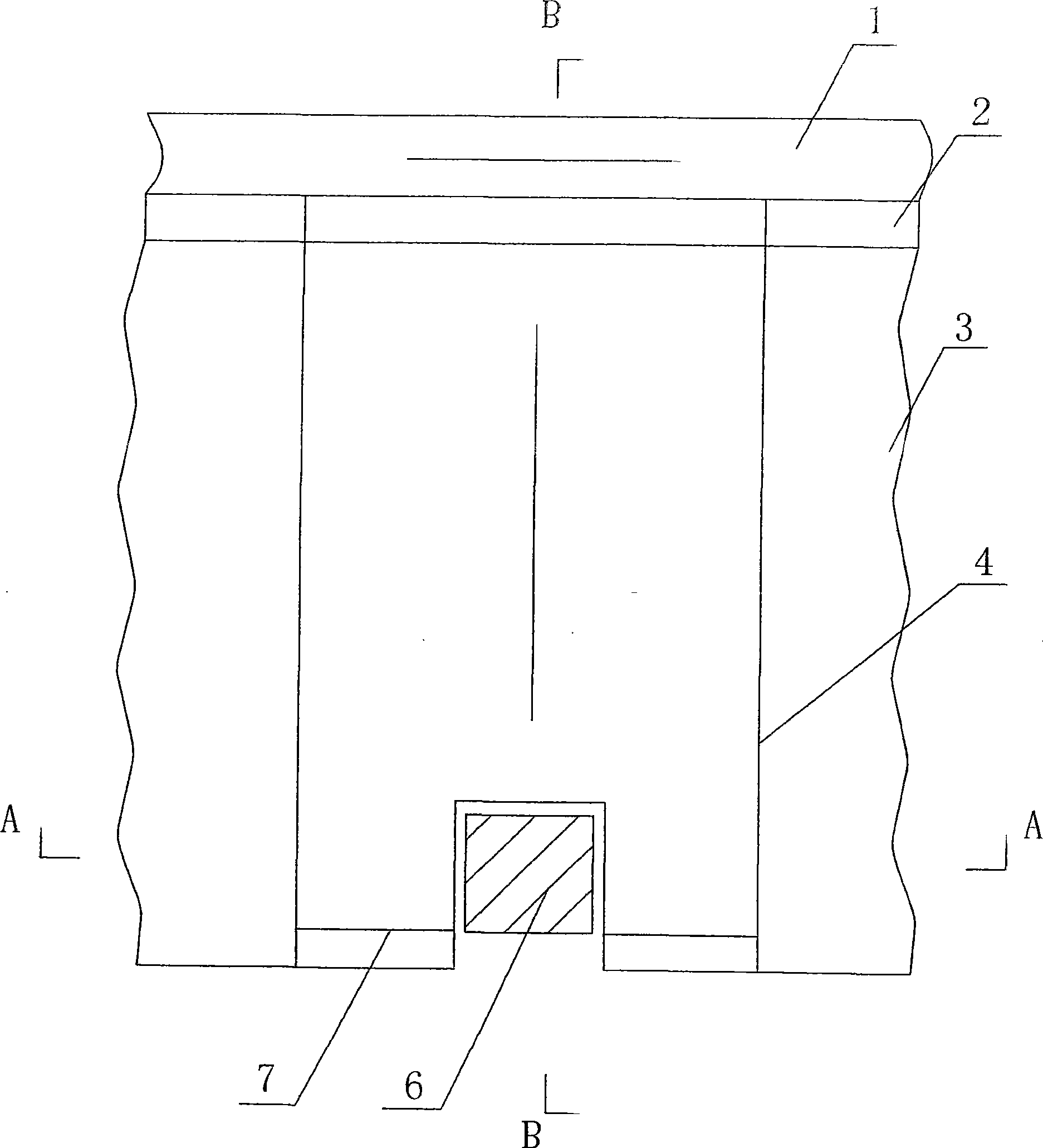
[0024] Example 1 Sealing device with front and rear equal width structures

[0025] The sealing device adopts a structure with equal width at the front and back, such as figure 1 , Figure 4 , 5 shown. The width (L=W) of the sealing device is 200 mm; the height (H) of the leading edge is 100 mm; the inclination angle (D) of the top plate is 0 degrees.

Embodiment 2

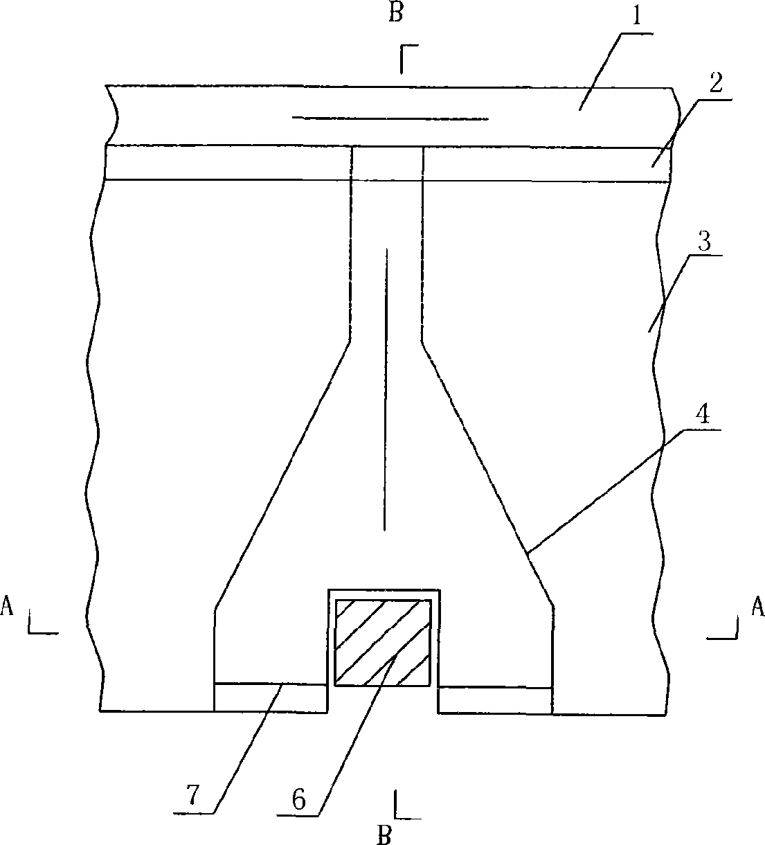
[0026] Example 2 Sealing device with wide front and narrow rear structure

[0027] The sealing device adopts a structure with a wide front and a narrow back, such as figure 2 As shown, in the top view projection, from front to back, the former seems to be composed of a horizontal rectangle with a hollowed out square, an isosceles trapezoid and a vertical rectangle. The frontal width (L) of the sealing device is 500 mm; the frontal height (H) is 80 mm; the width (W) of the sealing device corresponding to the passage of the horizontal flue interface part is 80 mm; the inclination angle (D) of the top plate is 5°.

Embodiment 3

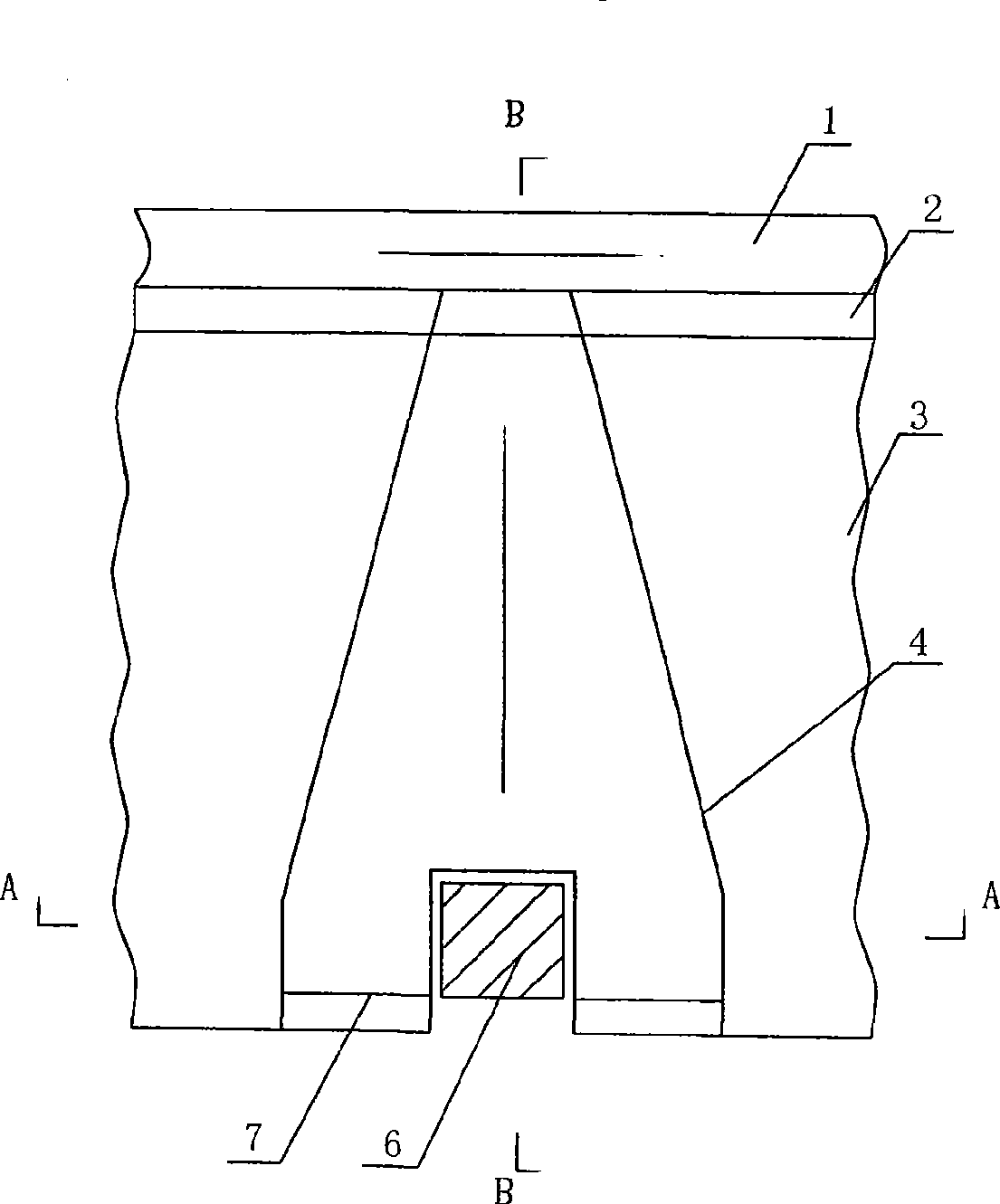
[0028] Example 3 Sealing device with wide front and narrow rear, inclined roof structure

[0029] The sealing device adopts a structure with a wide front and a narrow rear, and an inclined top plate, such as image 3 , as shown in Figure 7, its top view image is composed of a horizontal rectangle with a hollowed out square and a slender isosceles trapezoid; from the side view, its top plate has an upward sloping angle from front to back . The frontal width (L) of the sealing device is 350 mm; the frontal height (H) is 50 mm; the width (W) of the sealing device corresponding to the passage of the horizontal flue interface part is 50 mm; the inclination angle (D) of the top plate is 20°.


PUM


Abstract

The invention provides a method for sealing aluminium cell anode rods. The method is characterized in that a device capable of producing negative pressure is installed around each rod; and the flue gas originally overflowing through the clearance between the rods and a housing plate is reversely absorbed into a flue of an aluminum cell. The invention also correspondingly provides an anode rod sealing device specially designed for executing the method. The sealing device comprises side plates, a front end plate and a top plate and is characterized in that the sealing device consists of two side plates, the top plate and the front end plate and is a cavity device surrounding the anode rods from three faces; wherein (1) a grid structure is adopted on the front end of the device enclosing the anode rods from three faces; (2) the tail part of the device is welded with a plate-web girder and is communicated with a horizontal flue; and (3) the device is arranged on a horizontal housing plate and takes the horizontal housing plate as the bottom plate of the device. The sealing device can greatly reduce the leaked flue gas, thereby improving the working environment of an electrolysis shop, and creating good social and economic benefits.

Description

technical field [0001] The invention belongs to the technical field of aluminum electrolytic cell anodes, and relates to a sealing method and device for an anode guide rod of an aluminum electrolytic prebaking cell. Background technique [0002] At present, the seal between the anode guide rod and the horizontal cover plate of the aluminum electrolytic cell is all made of steel plate pressed asbestos cloth. However, the production practice shows that after a period of time, the asbestos cloth is damaged due to wear and impact with the guide rod; in addition, the inspection and replacement of the equipment by the relevant personnel of the enterprise is not timely, and as a result, a large amount of harmful gas in the tank will flow from the The gap between the anode guide rod and the horizontal cover plate escapes. [0003] As countries around the world pay more and more attention to environmental protection, how to improve the working environment of aluminum electrolytic ce...

Claims


Application Information

Patent Timeline
Patent Type & Authority Applications(China)
IPC IPC(8): C25C3/12
Inventor 戚喜全刘敬雄董慧马成贵吕定雄毛继红王德全
Owner NORTHEASTERN UNIV ENG & RES INST CO LTD
Why Eureka
Try Eureka