Regulation valve with accurately positioned valve core

A technology for precise positioning and regulating valves, applied in valve details, valve operation/release devices, valve lifts, etc., can solve problems such as large driving energy, difficult precise positioning, and no precise intermediate position

Active Publication Date: 2009-05-13
哈尔滨工程大学海能科技有限责任公司
View PDF2 Cites 11 Cited by
  • Summary
  • Abstract
  • Description
  • Claims
  • Application Information

AI Technical Summary

Problems solved by technology

"The disadvantage is that it is not easy to achieve precise positioning
Its disadvantages are: the structure is somewhat compl

Method used


Image

  • Regulation valve with accurately positioned valve core
  • Regulation valve with accurately positioned valve core

Examples


Embodiment Construction

[0017] Preferred embodiments of the present invention are given below and described in conjunction with the accompanying drawings.

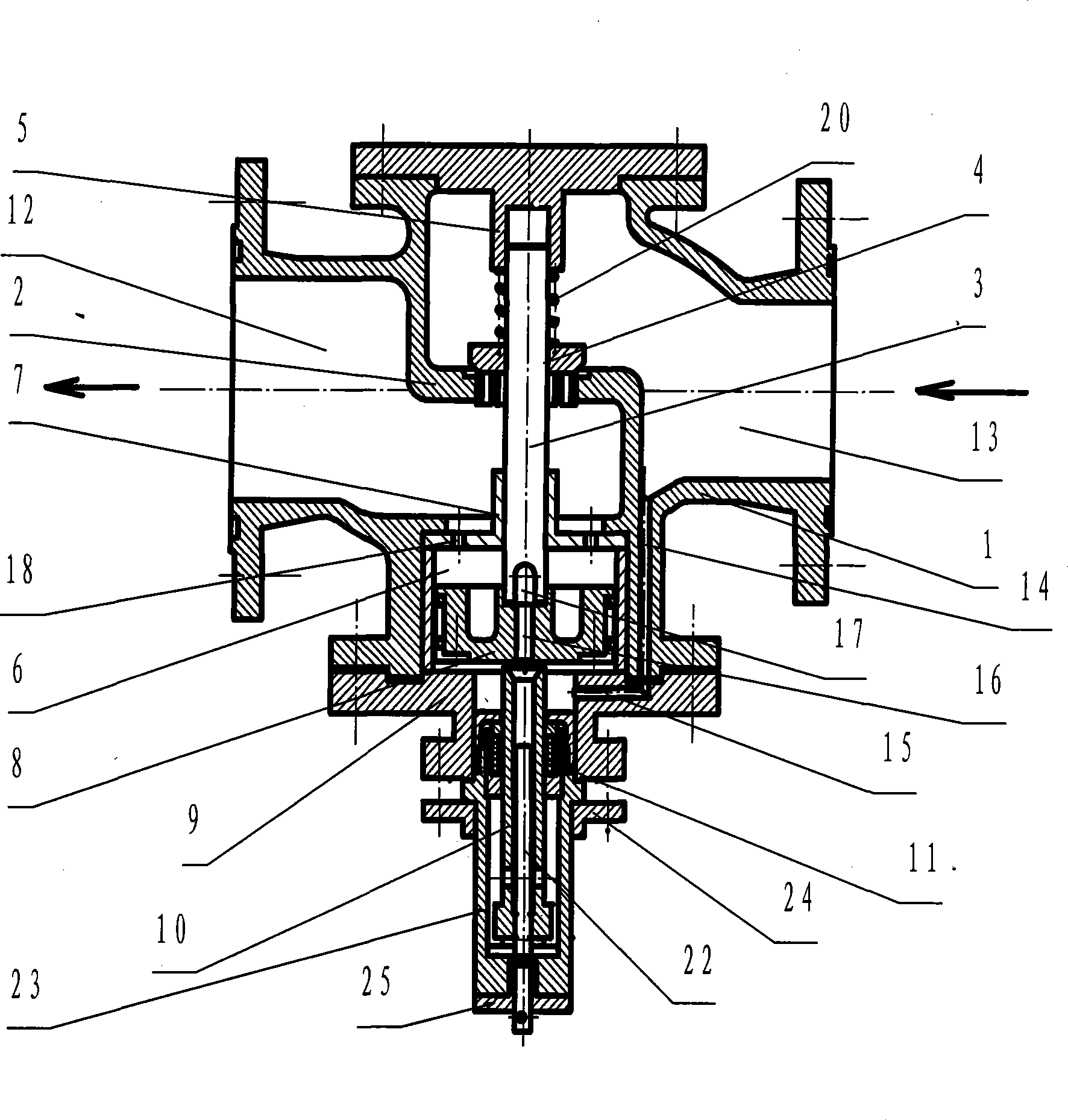
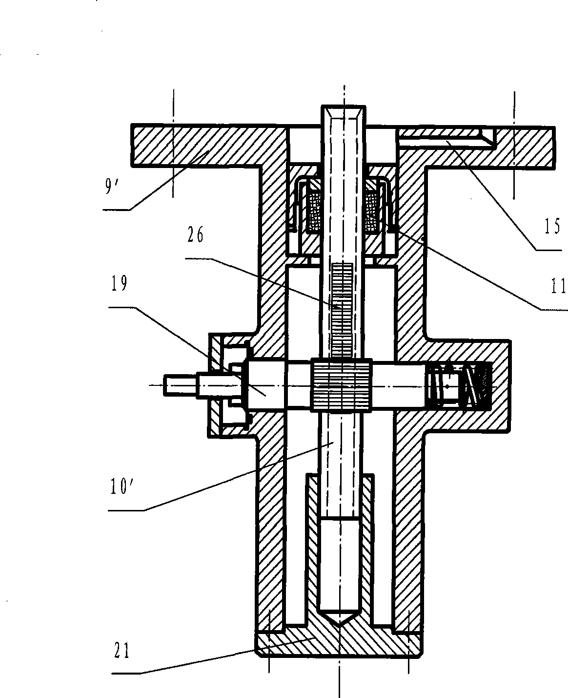
[0018] Such as figure 1 As shown, the regulating valve for precisely positioning the spool includes three parts: the valve body, the driving mechanism and the servo mechanism. The driving mechanism includes the driving cylinder 6, the piston 8 and the valve stem 3 with the spool 4; 9. Servo tube 10, adjusting rod 22, guide sleeve 23, sealing assembly 11 and guide sleeve cover 25; valve body 1 is a combination of a valve body with a conventional stop valve structure and a drive cylinder 6, and processed to guide and control Fluid through passage.

[0019] Four openings with flanges on the outer edge are processed on the valve body 1, that is, the controlled fluid inlet and outlet of the coaxial line, the drive cylinder port and the stem seat installation port of the coaxial line, and the two axes are orthogonal The three-section bending partitio...


PUM


Abstract

A regulating valve used for accurately positioning a valve plug and regulating pressure or flow rate of fluid in a fluid transportation pipeline is especially suitable for power station, petroleum and chemical department, belonging to the field of engineering elements or parts. The regulating valve comprises three parts which are a valve body, a driving cylinder and a servo mechanism, and the valve body having the conventional structure of a stop valve is combined with the driving cylinder that is internally provided with a piston into a whole; a channel used for drawing in the controlled fluid is also processed; the servo mechanism mainly includes a servo pipe and a screw gearing pair (or a pinion and rack gearing pair). The gap between the end surface of the servo pipe and the end surface of an axial aerial drainage hole in the center of the piston is regulated to change the differential pressure of the controlled fluid at the two sides of the piston, and the valve plug linked with the piston is further moved and is accurately balanced at the requested position. The regulating valve has the advantages that the mobile servo pipe has low power consumption (watt level), high positioning accuracy, large turndown ratio, high sensitivity, good stability and easy combination with a fluid control system having high intelligence.

Description

technical field [0001] The utility model relates to a regulating valve with a precisely positioned spool, which is used to regulate the fluid pressure or flow of the fluid conveying pipeline, and is especially suitable for power stations, petroleum, chemical and other departments. Belonging to the field of engineering components or components. Background technique [0002] The regulating valve on the fluid conveying pipeline is divided into external drive type and self-operated type according to the type of power source. The former is driven by hand, electricity or gas (steam) or liquid outside the fluid conveying pipeline, while the latter is The spool is driven by the self-energy of the controlled fluid such as steam or liquid in the fluid delivery pipeline. With the progress of society, the development of science and technology, the improvement of production technology and the improvement of automation, higher requirements are put forward for control valves, such as simp...

Claims


Application Information

Patent Timeline
IPC IPC(8): F16K31/124F16K27/00F16K1/38F16K1/34
Inventor 韩伟实沈明启韩旭刘春雨杨志达周杰栾秀春
Owner 哈尔滨工程大学海能科技有限责任公司
Why Eureka
Try Eureka