Cutting tool assembly for peeling three bundle of parallel core wires and peeling machine using the same

A cutting tool assembly and stripping machine technology, which is applied in the installation of line/collector parts, electrical components, cables, etc., can solve problems such as low production efficiency, unpeeled wires, and shearing of conductive cores, and achieve improved stripping efficiency and operation The effect of convenience and simple structure

Inactive Publication Date: 2009-05-13
LINOYA ELECTRONIC TECHNOLOGY CO LTD
View PDF0 Cites 31 Cited by
  • Summary
  • Abstract
  • Description
  • Claims
  • Application Information

AI Technical Summary

Problems solved by technology

[0002] Wires and cables are widely used in daily life. Generally, the conductive core of the wire is wrapped by an insulating sheath. The insulating sheath is usually made of polyvinyl chloride. When wiring, it is usually necessary to peel off the sheath at the end of the wire and remove it. Expose the conductive core to connect the conductive core to other conductors; in order to peel off the sheath at the end of the wire smoothly, the most traditional method is to burn the sheath at the end of the wire with fire to soften the sheath, and quickly use your hands or Other tools tear it off, but the peeled skin is easy to stick to hands or tools, and because the fire temperature is difficult to control, there is also the possibility that the conductive core is oxidized
Later, some people used tools such as wire strippers of various styles,

Method used


Image

  • Cutting tool assembly for peeling three bundle of parallel core wires and peeling machine using the same
  • Cutting tool assembly for peeling three bundle of parallel core wires and peeling machine using the same
  • Cutting tool assembly for peeling three bundle of parallel core wires and peeling machine using the same

Examples


Embodiment Construction

[0019] The present invention will be further described below in conjunction with the accompanying drawings and specific embodiments.

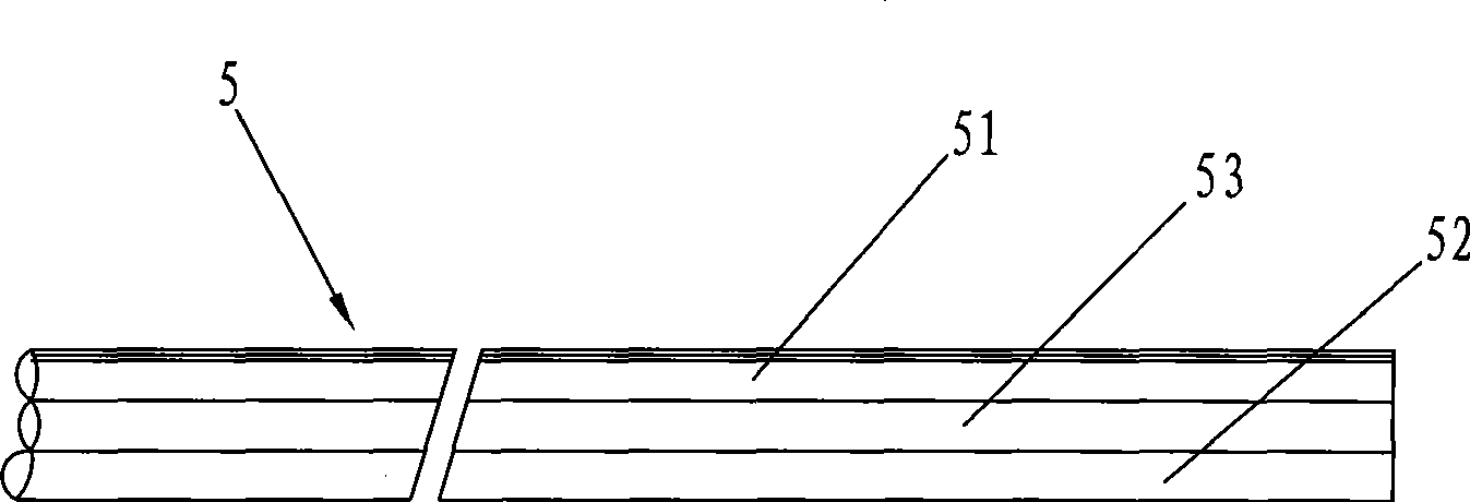
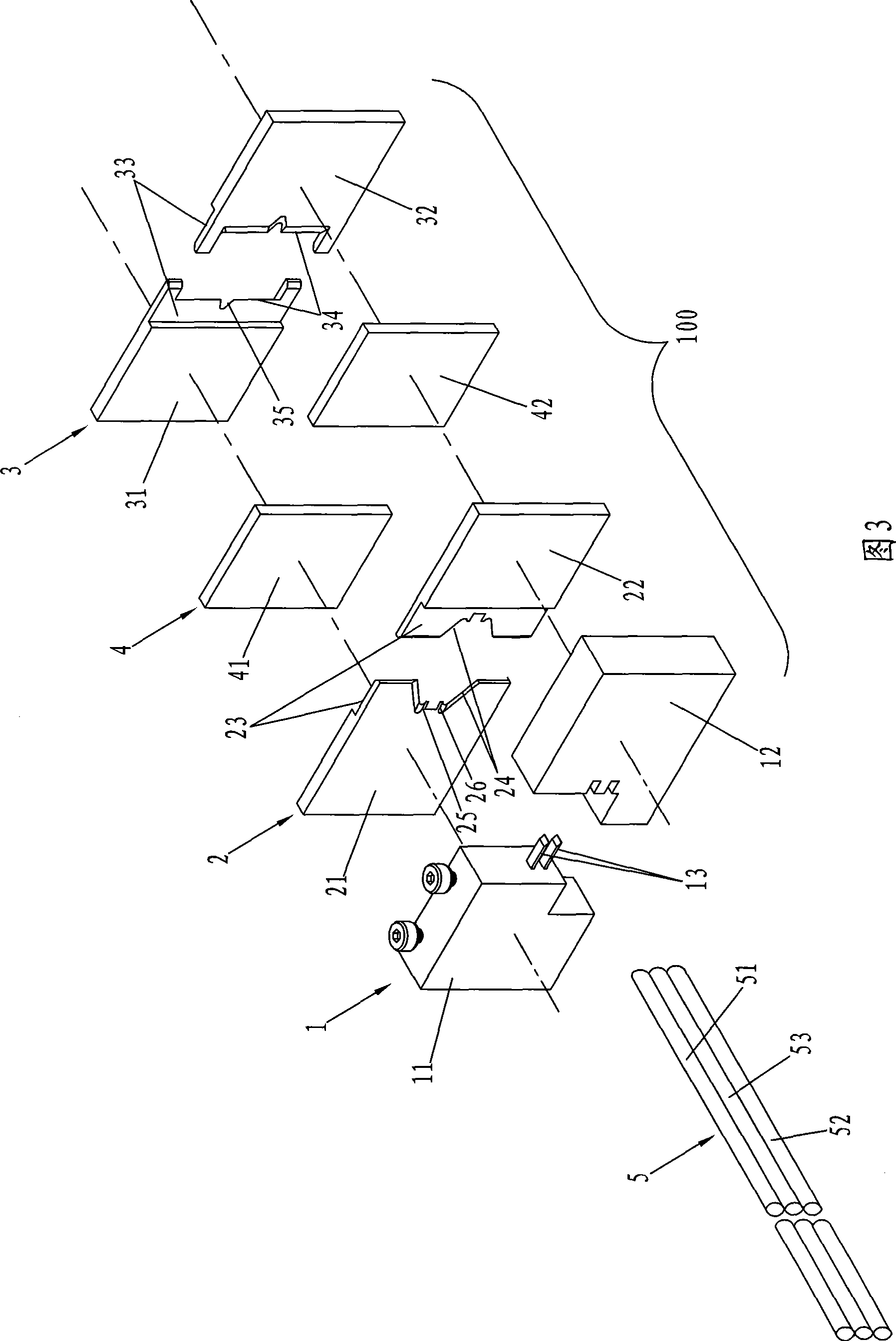
[0020] see Figure 1 to Figure 4 As shown, a cutter assembly 100 for stripping three bundles of parallel core wires is a tool for pre-cutting three bundles of parallel core wire sheaths. Cutting die 3 and spacer plate 4, wherein:

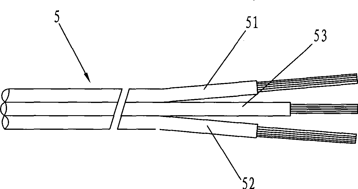
[0021] The bifurcated die 1 is used to divide the core wires 51, 52, 53 of the three bundles of parallel core wires 5; it includes a male die 11 and a female die 12. The mold surface is provided with two upper and lower parallel bifurcated cutters 13, which are beneficial to the bifurcated cutters to split the three bundles of parallel core wires in advance.

[0022] The first cutting die 2 is used for correspondingly cutting the sheaths of the side core wires 51 and 52 of the three bundles of parallel core wires 5; wherein the first cutting die 2 is composed of a first die die 21 and a second die die 22 The clamp...


PUM


Abstract

The invention relates to a three-bundle parallel core wire stripping toolbox and a stripping machine using the toolbox. The toolbox first branches off three bundles of parallel core wires by a branch cutting die, then precutting process is carried out on skins of the core wires at two sides and in the middle by a first cutting die and a second cutting die respectively, and a partition board arranged between the first cutting die and the second cutting die can ensured that a certain distance exists between the cutting positions of the core wires at two side parts and the core wire in the middle, so as to meet market requirements. The stripping machine precuts the skin at the end parts of the core wires by the toolbox driven by a first cylinder, and then drives the toolbox and the first cylinder to move along the core wire extending direction by a second cylinder, so that the toolbox can move to strip the precut skins under the condition that the core wires keep motionless, therefore, the manual work manner in the prior art can be replaced, the skins at the end parts of the core wires can be stripped off rapidly and conveniently, and the invention is suitable for mass production is high, thus improving the stripping efficiency.

Description

technical field [0001] The invention relates to wire and cable stripping technology, in particular to a cutter assembly for peeling three bundles of parallel core wires and a peeling machine using the cutter assembly. Background technique [0002] Wires and cables are widely used in daily life. Generally, the conductive core of the wire is wrapped by an insulating sheath. The insulating sheath is usually made of polyvinyl chloride. When wiring, it is usually necessary to peel off the sheath at the end of the wire and remove it. Expose the conductive core to connect the conductive core to other conductors; in order to peel off the sheath at the end of the wire smoothly, the most traditional method is to burn the sheath at the end of the wire with fire to soften the sheath, and quickly use your hands or Other tools tear it off, but the peeled skin is easy to stick to hands or tools, and because the fire temperature is difficult to control, there is also the possibility that th...

Claims


Application Information

Patent Timeline
IPC IPC(8): H02G1/12H01R43/28
CPCH02G1/127
Inventor 白建文
Owner LINOYA ELECTRONIC TECHNOLOGY CO LTD
Why Eureka
Try Eureka