Composite switch reluctance motor

A switched reluctance motor, hybrid technology, applied in the direction of electrical components, electromechanical devices, magnetic circuit static parts, etc., can solve the problems of low slot full rate, difficult process, difficult winding off-line, etc., and increase the usable area , high motor efficiency, and the effect of improving the performance-to-volume ratio and performance-to-weight ratio

Inactive Publication Date: 2009-05-13
HARBIN INST OF TECH
View PDF0 Cites 19 Cited by
  • Summary
  • Abstract
  • Description
  • Claims
  • Application Information

AI Technical Summary

Problems solved by technology

[0004] The present invention proposes a hybrid switched reluctance motor in order to solve the shortcomings of the existing switched reluctance motor structure, such as difficulty in winding off the assembly line, high process difficulty, and low slot full rate.

Method used


Image

  • Composite switch reluctance motor
  • Composite switch reluctance motor
  • Composite switch reluctance motor

Examples


specific Embodiment approach 1

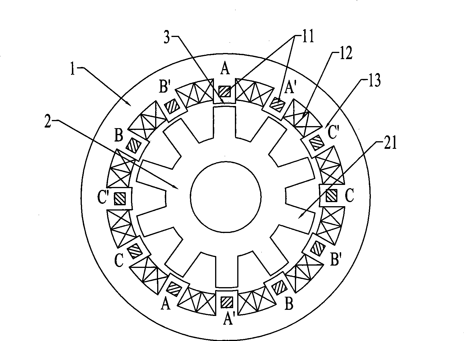
[0011] Specific implementation mode one: combine image 3 Describe this embodiment, the hybrid switched reluctance motor of this embodiment is made up of stator 1 and rotor 2; Stator 1 is made up of permanent magnet 11, field winding 12 and stator core 13; The outer circle of the rotor core 21 of rotor 2 and stator An air gap 3 is provided between the inner circles of the iron core 13 , the excitation winding 12 is embedded in the tooth slot of the stator iron core 13 , and the permanent magnet 11 is embedded in the teeth of the stator iron core 13 along the axial direction. It moves by the reluctance torque generated by the electric excitation magnetic potential of the radial excitation winding 12 on the stator and the permanent magnet magnetic potential of the permanent magnet 11 of the stator teeth.

specific Embodiment approach 2

[0012] Specific implementation mode two: combination image 3 Describe this embodiment, the difference between this embodiment and specific embodiment 1 is that the permanent magnet 11 provided on the teeth of the stator core 13 is a long strip permanent magnet, and the magnetization direction of the permanent magnet 11 is the same as that of the field winding 12 after energization. The direction of the magnetic field is the same. Other compositions and connection methods are the same as those in Embodiment 1.

specific Embodiment approach 3

[0013] Specific implementation mode three: combination image 3 This embodiment is described. The difference between this embodiment and the first embodiment is that the number of permanent magnets 11 provided on the teeth of the stator core 13 is equal to the number of teeth of the stator core 13 . Other compositions and connection methods are the same as those in Embodiment 1.


PUM


Abstract

The invention relates to a mixed switch reluctance motor, belonging to the electric motor field. The invention overcomes the defects that the installation of a winding is difficult, the manufacturing process is comparatively difficult, the space factor is low, and the like due to the structure of the existing switch reluctance motor. In the invention, the mixed switch reluctance motor consists of a stator and a rotor, wherein, the stator is composed of a permanent magnet, an exciting winding and a stator core; an air gap is arranged between the excircle of the rotor core of the rotor and the inner circle of the stator core, the exciting winding is embedded in an tooth socket of the stator core, while the permanent magnet is embedded into the tooth part of the stator core along the axis direction. In the invention, a high-performance tangential magnetizing permanent magnet is used, and the permanent magnet is embedded into the tooth part of the stator core along the axis direction, thus forming a mixed excitation switch reluctance motor; compared with the existing mixed excitation switch reluctance motor, the motor in the invention has unchanged number of permanent magnets and increased usable area of the stator groove winding, thus improving the performance and volume ratio and the performance and weight ratio of the motor of the invention, reducing cost and simplifying manufacturing process. The motor of the invention can be used as an electric motor and an electric generator.

Description

technical field [0001] The invention relates to a hybrid excitation switched reluctance motor and belongs to the field of motors. Background technique [0002] Existing switched reluctance motors such as figure 1 As shown, the stator and rotor of the motor are salient pole structures. By sequentially energizing the stator field windings, the stator poles interact with the rotor poles to generate torque. Since there are neither windings nor permanent magnets on the rotor, the structure of the motor is simple and the operation is reliable. But precisely because neither the stator nor the rotor uses permanent magnets, in order to obtain a large output torque, a large excitation power is required, which not only limits the performance-to-volume ratio of the motor, but also increases the cost of the drive system. [0003] Existing hybrid excitation switched reluctance motors such as figure 2 As shown, there are long strip permanent magnets in the stator slot, and the permane...

Claims


Application Information

Patent Timeline
Patent Type & Authority Applications(China)
IPC IPC(8): H02K29/00H02K1/17
Inventor 吴红星寇宝泉杨锡辉刘奉海贵献国
Owner HARBIN INST OF TECH
Why Eureka
Try Eureka