Multi-frequency band electronic device and multi-frequency band signal processing method

An electronic device, multi-band technology, applied in the direction of electrical components, automatic power control, etc., can solve problems such as increasing system complexity and cost

Active Publication Date: 2009-05-13
RICHWAVE TECH CORP
View PDF0 Cites 5 Cited by
  • Summary
  • Abstract
  • Description
  • Claims
  • Application Information

AI Technical Summary

Problems solved by technology

In this way, it is bound to increa...

Method used


Image

  • Multi-frequency band electronic device and multi-frequency band signal processing method
  • Multi-frequency band electronic device and multi-frequency band signal processing method
  • Multi-frequency band electronic device and multi-frequency band signal processing method

Examples


Embodiment Construction

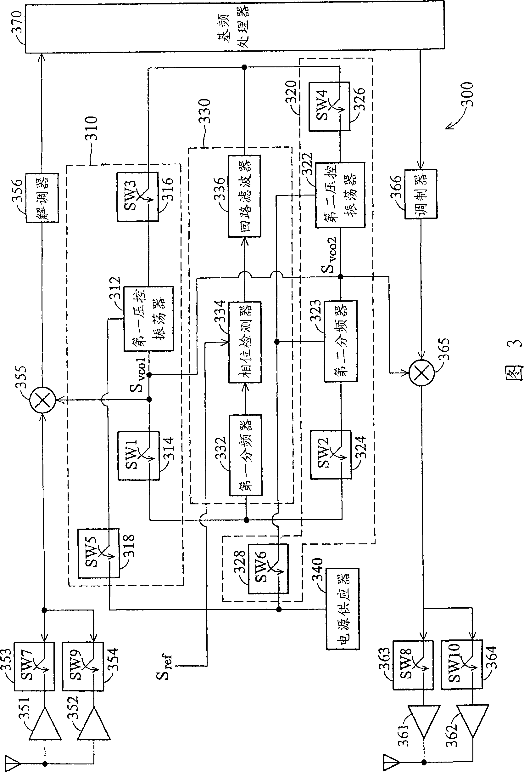
[0058] FIG. 3 is a multi-band electronic device 300 according to an embodiment of the invention. The multi-band electronic device 300 supports transceivers operating in multiple different frequency bands (for simplicity, two frequency bands are taken as an example; eg, 2.4-2.5 GHz, 5.0-6.0 GHz). The multi-band electronic device 300 includes first, second and third circuit parts 310, 320, 330, a power supply 340, low noise amplifiers 351, 352, power amplifiers 361, 362, switches 353, 354, 363, 364, mixing Frequency converters 355, 365, a demodulator 356, a modulator 366, and a baseband processor 370. The first circuit part 310 includes a first voltage controlled oscillator 312 , first, third and fifth switches 314 , 316 , 318 . The second circuit part 320 includes a second voltage-controlled oscillator 322 , a second frequency divider 323 , second, fourth, and sixth switches 324 , 326 , and 328 . The third circuit part 330 includes a first frequency divider 332 , a phase dete...


PUM


Abstract

The invention provides a multiband electronic device and a multiband signal processing method. The multiband electronic device comprises a first circuit part, a second circuit part and a third circuit part. According to a switching signal, the first circuit and the third circuit selectively form a first phase-locked loop frequency synthesizer, and at the same time the second circuit and the third circuit do not form a phase-locked loop, and the output range of the first phase-locked loop frequency synthesizer is in a first frequency band; or according to the switching signal, the second circuit and the third circuit selectively form a second phase-locked loop frequency synthesizer, and at the same time the first phase-locked loop frequency synthesizer forms a broken circuit, and the output range of the second phase-locked loop frequency synthesizer is in a second frequency band; and the first frequency band and the second frequency band are not completely overlapped.

Description

technical field [0001] The present invention relates to a phase-locked loop frequency synthesizer, in particular to a multi-band phase-locked loop frequency synthesizer capable of synthesizing desired frequencies in multiple frequency bands. Background technique [0002] A phase locked loop is an electronic control system that generates a signal that locks the phase of a reference signal. figure 1 is a block diagram of a known PLL 100 . The phase locked loop 100 includes a phase detector 110 , a loop filter 120 , and a voltage controlled oscillator 130 . The phase detector 110 is generally a mixer, which compares the difference in frequency and phase between the reference signal Sref and the output signal Svco of the voltage-controlled oscillator 130 , and outputs a difference signal to the loop filter 120 . The loop filter 120 drives the voltage-controlled oscillator 130 according to the difference signal, so as to maintain the phase difference between the output signal S...

Claims


Application Information

Patent Timeline
IPC IPC(8): H03L7/18H03L7/08
Inventor 王一峰邓维康
Owner RICHWAVE TECH CORP
Why Eureka
Try Eureka