Positioning device

a technology of positioning device and positioning axis, which is applied in the direction of dynamo-electric machines, printers, instruments, etc., can solve the problems of limited accuracy characteristic, inability to optimize the performance the drive unit can be considered oversized, so as to improve the dynamic response of the first drive unit, reduce dissipation, and accurate positioning of objects

Inactive Publication Date: 2005-09-15
ASML NETHERLANDS BV
View PDF4 Cites 1 Cited by
  • Summary
  • Abstract
  • Description
  • Claims
  • Application Information

AI Technical Summary

Benefits of technology

[0017] Additionally, the dissipation that occurs during acceleration or deceleration may deteriorate the overall process since it may result in thermal stresses in the object or object table.
[0020] In the drive arrangement of the present invention, as described above, the required force to accelerate or decelerate the object is at least partly provided by the permanent magnet system. Therefore, the actual force requirement of the first drive unit for acceleration or deceleration is reduced, resulting in a reduced dissipation during acceleration or deceleration. This reduced dissipation will enable a more stable (with respect to temperature) environment resulting in an improvement of the accuracy of the overall process. Since the actual force requirements of the first drive unit are reduced by the presence of the permanent magnet system, the first drive unit can be made smaller and lighter. This may result in an improved dynamic response which will enable a more accurate positioning of the object.
[0021] In case the first drive unit has become lighter, the overall mass to be displaced by the second drive unit may also have decreased. In this case, the force requirement for the second drive unit has also decreased resulting in a reduced dissipation of the second drive unit. The reduced dissipation occurring in either the first or second (or both) drive units may also favorably affect the requirements of the cooling unit (or units) that cool the drive units. Furthermore, reducing the force requirements of either of the drive units can simplify the design requirements for the amplifiers that supply the power to the drive units.
[0022] Alternatively, the arrangement according to the present invention can also be applied to increase the productivity of the apparatus wherein the positioning device is used by applying higher acceleration and deceleration. With the present invention, this may be achieved without an increase in dissipation of the first and second drive unit.
[0032] In yet another embodiment according to the present invention, the function describing the force of the permanent magnet system has a first derivative substantially equal to zero for said first position. In such an arrangement, the stiffness of the permanent magnet system with respect to the first direction is substantially zero in said first position. This provides an advantage with respect to the isolation of vibrations between the object table and the second part of the first drive unit attached to the second drive unit. Since the force generated by the permanent magnet system is substantially independent of the relative position of the parts of the permanent magnet system in the first direction in the mentioned position, vibrations occurring on the second drive unit will hardly be transmitted to the object, enabling an accurate positioning of the object.
[0033] In still another embodiment of the present invention, the permanent magnet system is constructed and arranged to generate a force in a second direction between the object and the moving part of the second drive unit, the second direction being preferably perpendicular to the first direction. In such an arrangement the permanent magnet system can at least partly provide the acceleration and deceleration force required to displace the object table in both first and second directions. This may result in either a reduction in dissipation in the first drive unit and / or the second drive unit. Introducing this permanent magnet system may enable the use of a smaller (and lighter) first drive unit, thereby improving the dynamic response of the first drive unit and possibly a reduction in the force requirements for the second drive unit. In such an arrangement, the second drive unit may, as an example, be a planar motor or an H-bridge type drive arrangement.

Problems solved by technology

The positioning device comprises linear motors for positioning an object that is mounted on the stage by a first drive unit over comparatively small distances with a high accuracy, the first drive unit can be positioned in at least one direction by a second drive unit over comparatively large distances with a limited accuracy characteristic.
However, because of the different operating conditions and the different requirements during the different phases described above, the design of the first drive unit requires a give and take to combine the force requirements, during acceleration and deceleration, with the accuracy requirements, during the constant velocity phase.
This results in a non-optimal performance of the first drive unit.
During the constant velocity phase however, the drive unit can be considered oversized because the force requirements are much less during that phase.
This oversized drive unit may not have an optimal dynamic response during the constant velocity phase.
Since part of the weight of the drive unit has to be displaced as well, the overall weight to be accurately positioned can be significantly higher than the sole weight of the object table, requiring additional control effort.
The different force requirement during acceleration (or deceleration) and during the constant velocity phase also hinder an optimal design for the amplifier (e.g. a current amplifier) that provides the power to the different actuators.
Additionally, the dissipation that occurs during acceleration or deceleration may deteriorate the overall process since it may result in thermal stresses in the object or object table.

Method used


Image

  • Positioning device
  • Positioning device
  • Positioning device

Examples


embodiments

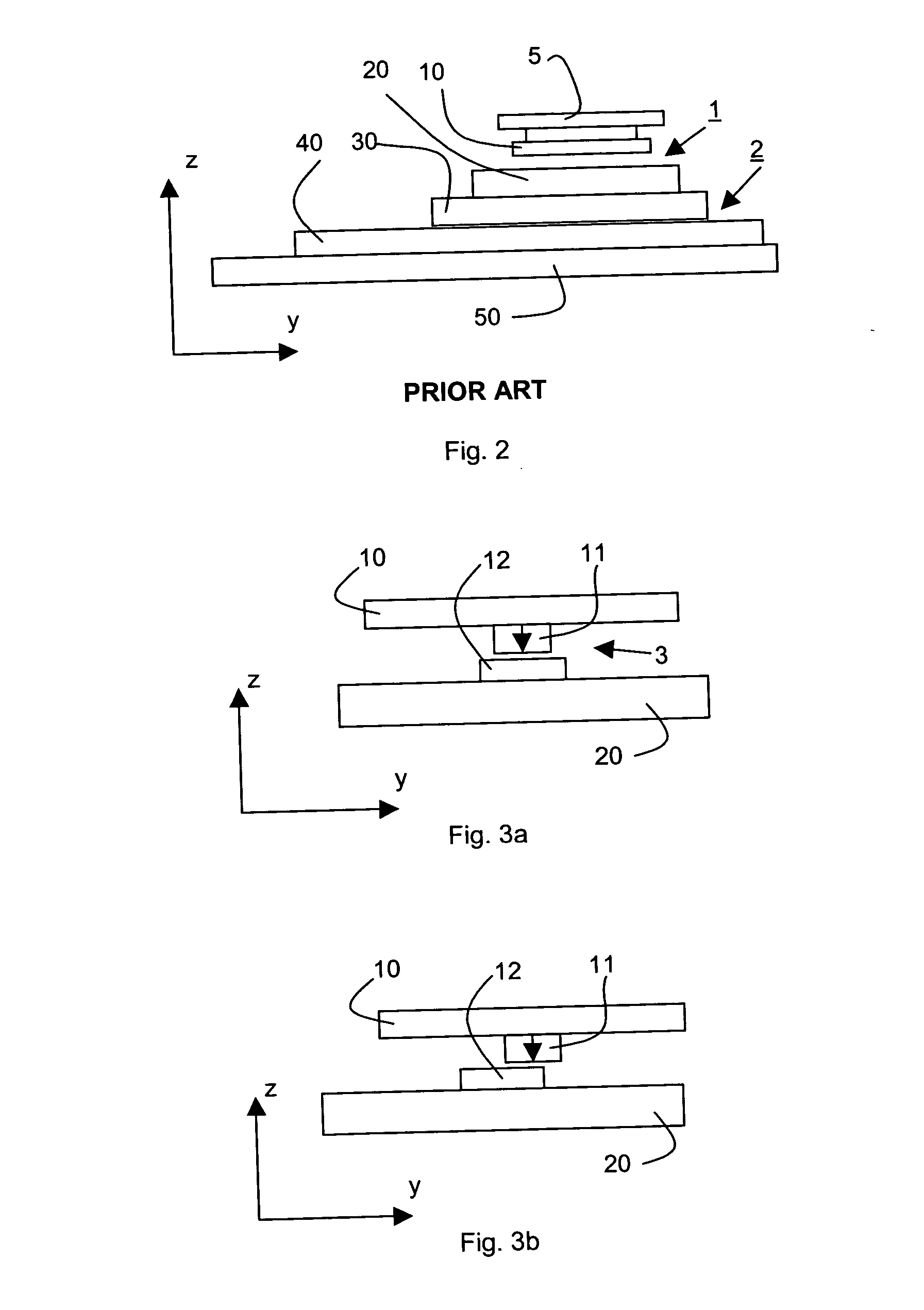
[0084]FIG. 2 schematically depicts a positioning device as known in the art, comprising a first drive unit 1 mounted on a second drive unit 2. Such a positioning device can be applied to position an object table provided with a substrate or a patterning device. The first drive unit 1 comprises a first part 10 attached to an object table 5 and a second part 20 attached to a first part 30 of the second drive unit. The second drive unit 2 further comprises a second part 40 that can be mounted, as an example, to a frame or a balance mass 50. The first and second part of the second drive unit 2 can be positioned relative to each other over comparatively large distances in at least one direction (Y-direction in FIG. 2).

[0085] Typically, the displacement of >500 mm can be obtained with a micrometer accuracy. As an example, the second drive unit may comprise a planar motor, an H-type drive or a linear motor construction. Such drive arrangements may be applied in a lithographic apparatus as...


PUM


Abstract

A positioning device for positioning an object is presented. The positioning device comprises a first drive unit and a second drive unit for positioning the object. The first drive unit has a first part connected to the object and a second part connected to a first part of the second drive unit. The positioning device further comprises a permanent magnet system constructed and arranged to provide at least part of the force for accelerating or decelerating the object.

Description

RELATED APPLICATIONS [0001] This application is a Continuation-in-Part application and claims benefit of U.S. application Ser. No. 10 / 796,289, filed on Mar. 10, 2004, the entire contents of which are hereby incorporated into the present application by reference.BACKGROUND OF THE INVENTION [0002] 1. Field of the Invention [0003] The present invention relates to a positioning device for positioning an object. [0004] 2. Description of the Related Art [0005] Positioning devices that are capable of accurately displacing system components or objects are employed in numerous technologies, including, for example, lithographic fabrication processes. A lithographic apparatus can be used, for example, in the manufacture of integrated circuits (ICs). In such a case, a patterning device may be used to generate a desired circuit pattern corresponding to an individual layer of the IC, and this pattern can be imaged onto a target portion (e.g. comprising one or more dies) on a substrate (silicon wa...

Claims


Application Information

Patent Timeline
Patent Type & Authority Applications(United States)
IPC IPC(8): H01L21/027G03B27/54G03B27/58G21K5/10H02K1/22
CPCG03F7/70758H02K2201/18H02K41/0356
Inventor SCHMIDT, ROBERT-HAN MUNNIG
Owner ASML NETHERLANDS BV
Why Eureka
Try Eureka