
Method and apparatus for acquiring optical power, and optical line terminal

An optical line terminal and optical power technology, applied in the field of optical networks, can solve problems such as interruption of normal services, manual operation, measurement errors, etc., and achieve the effects of reducing labor costs, facilitating system expansion, and maintaining good maintainability.

Active Publication Date: 2009-05-13
HUAWEI TECH CO LTD
View PDF0 Cites 9 Cited by
  • Summary
  • Abstract
  • Description
  • Claims
  • Application Information

AI Technical Summary

Problems solved by technology

In the process of realizing the present invention, the inventor found that the prior art has at least the following disadvantages: manual operation is required, which increases labor costs; normal business needs to be interrupted during measurement, and real-time measurement cannot be performed
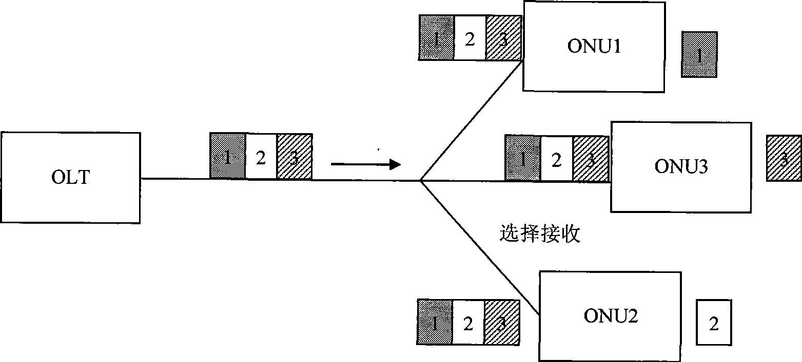
In the process of realizing the present invention, the inventor found that the prior art 2 has at least the following disadvantages: it is impossible to determine the optical power value of which ONU is currently being measured, and it is also impossible to selectively measure the optical power of the required ONU
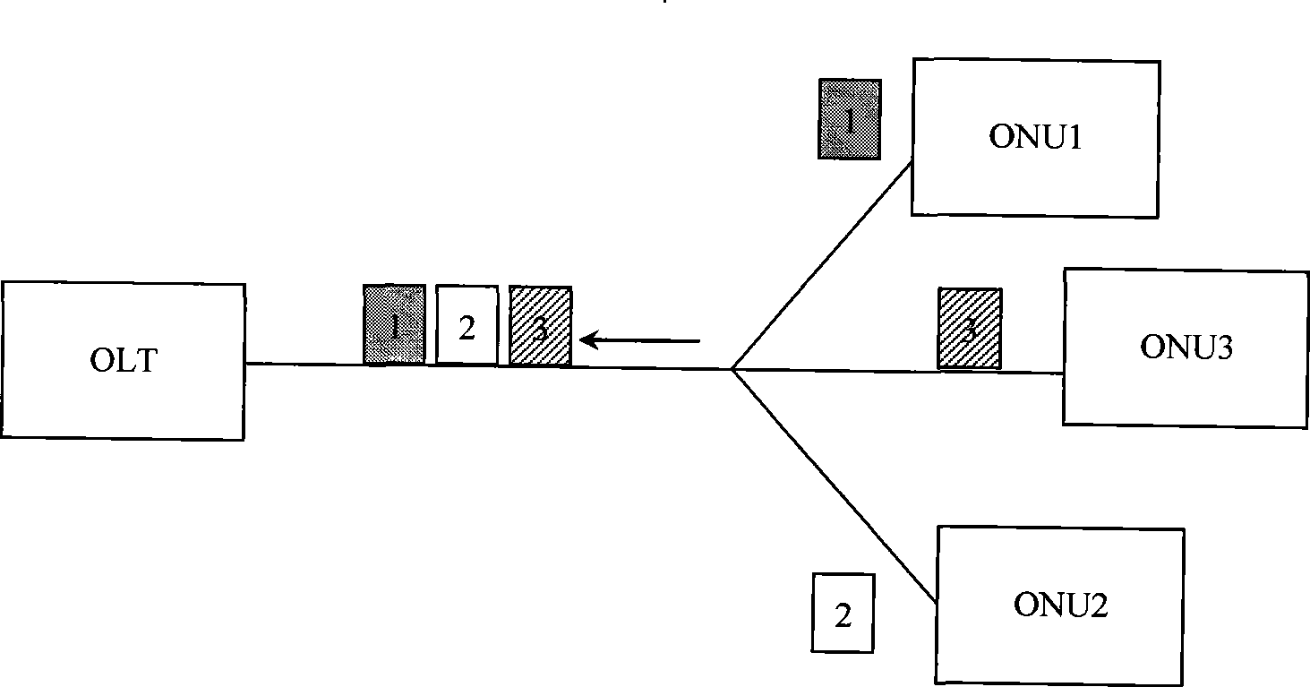
In the process of realizing the present invention, the inventor found that the prior art 3 has at least the following disadvantages: the estimated arrival time of the ONU signal to be tested needs to be written into the counter inside the conversion initialization module in advance, and the counter triggers the analog / digital conversion according to the time Due to system errors and link delays, the signal arriving when the counter finishes counting may not be the ONU optical signal to be measured, which will cause measurement errors

Method used


Image

  • Method and apparatus for acquiring optical power, and optical line terminal
  • Method and apparatus for acquiring optical power, and optical line terminal
  • Method and apparatus for acquiring optical power, and optical line terminal

Examples


Embodiment 1

[0045] see Figure 9 , the embodiment of the present invention provides a method for obtaining optical power, which is applied to a point-to-multipoint passive optical network communication system. In this embodiment, it is used to judge whether it is necessary to obtain the ONU in the received uplink signal according to the identification information. The method of optical power, and adopts the method of sampling and judging whether it needs to be obtained according to the identification at the same time. After judging that it needs to be obtained, start recording the sampling signal, which specifically includes the following steps:

[0046] Step 101: receiving uplink signals from at least two ONUs in the PON, performing power sampling on the received uplink signals, and extracting ONU identification information from the received uplink signals;

[0047] Sampling can be implemented with an ADC, see Figure 10 , the ADC in the power measurement circuit is connected to the amp...

Embodiment 2

[0065] see Figure 12 , the embodiment of the present invention also provides a method for obtaining optical power, which is applied to a point-to-multipoint passive optical network communication system. In this embodiment, it is used to judge whether it is necessary to obtain the ONU in the received uplink signal according to the identification information. The method of optical power, and adopts the method of first judgment, judgment needs to be obtained and then triggers sampling, which specifically includes the following steps:

[0066] Step 201: receiving uplink signals from at least two ONUs in the PON, and extracting the identification information of the ONUs from the received uplink signals;

[0067] Step 202: judging whether it is necessary to obtain the optical power of the ONU corresponding to the extracted identification information, if yes, then perform step 203; otherwise, end;

[0068] Step 203: Sampling the current uplink signal;

[0069] Step 204: Perform da...

Embodiment 3

[0079] see Figure 15 , the embodiment of the present invention also provides a method for obtaining optical power, which is applied in a point-to-multipoint passive optical network communication system, by pre-allocating time slots, and judging according to the upload start time of the ONU in the received uplink signal Whether it is necessary to obtain the optical power of the ONU, specifically include the following steps:

[0080] Step 301: the GMAC of the OLT allocates a fixed time slot for each T-CONT (transmission container) in the PON according to the DBA (Dynamic Bandwidth Assignment, dynamic bandwidth allocation) algorithm, and each ONU can contain one or more T-CONTs, The time slot allocated to the T-CONT determines the upload start time and upload end time of the ONU, thereby determining the upload sequence of multiple ONUs.

[0081] Among them, T-CONTs can be distinguished by Alloc-IDs (allocation identifiers), and there is a unique correspondence between Alloc-IDs...


PUM


Abstract

The invention discloses a method for acquiring optical power, a device and OLT thereof, belonging to the optical network field. The method comprises the following steps: receiving uplink signals from at least two optical network units; determining whether the optical power of the optical network unit is required or not according to the identification information or uploading time of the optical network unit in uplink signals; if so, the optical power of the optical network unit is acquired. The device comprises a receiving module, a judging module and an acquiring module. The OLT comprises ADC, a memory and a medium access control unit, wherein the medium access control unit is connected with the memory or connected with the ADC. By adopting the invention, the optical power of the ONU can be accurately acquired so that the cost is saved, and the acquisition can be realized at any time without interrupting normal services; the system has the advantages of easy expansion, good maintainability and lower maintenance cost; the optical power can be selectively acquired, the system can control start time and finish time of acquisition, thereby greatly improving the rate of accuracy.

Description

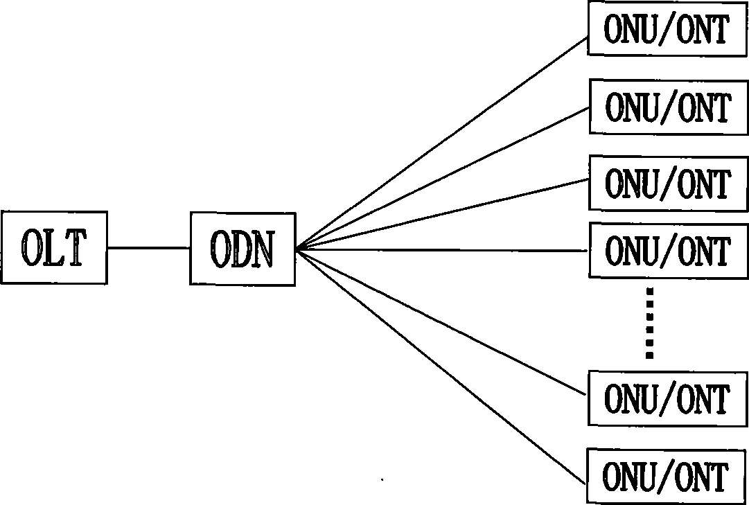
technical field [0001] The invention relates to the field of optical networks, in particular to a method, device and optical line terminal for obtaining optical power. Background technique [0002] PON (Passive Optical Network, Passive Optical Network) technology is a point-to-multipoint optical fiber access technology. see figure 1 , PON has a tree topology, which consists of ODN (Optical Distribution Network, Optical Distribution Network), OLT (Optical Line Terminal, Optical Line Terminal) on the office side, and ONU (Optical Network Unit, Optical Network Unit) or ONT on the user side (Optical Network Terminal, Optical Network Terminal). The so-called "passive" means that the ODN does not contain any active electronic devices and electronic power supplies, and is all composed of passive devices, such as optical splitters (Splitter), so the management and maintenance costs of PON are relatively low. [0003] In the GPON (Gigabit Passive Optical Network) system, the trans...

Claims


Application Information

Patent Timeline
IPC IPC(8): H04B10/12H04B10/17H04B10/08H04B10/075
Inventor 杨素林徐之光
Owner HUAWEI TECH CO LTD
Learn More