
Blanket machine

A punching machine and punching knife technology, which is applied to devices for cutting by nibbling, shearing devices, devices for shearing and forming blanks, etc. and other problems, to achieve the effect of improving the quality of shearing section, improving the precision of punching, and improving the efficiency of punching.

Inactive Publication Date: 2009-05-20
JINAN CASTING FORGING MACHINERY INST
View PDF0 Cites 6 Cited by
  • Summary
  • Abstract
  • Description
  • Claims
  • Application Information

AI Technical Summary

Problems solved by technology

The biggest disadvantage of the above methods is that the quality of the shear section of the car longitudinal beam is poor, and defects such as collapse, deformation, and tearing are prone to occur.
After the above cutting process, the "U" beam often needs to be corrected by manual shaping or removing part of the length. Not only the production efficiency is low, but also the labor intensity is high, and the cutting tool wears quickly and the noise is quite large. Can not meet the requirements of national environmental protection standards
Existing punching machines use fixed molds and fixed knives, and can only punch one type of "U" beam. If you need to punch other types of "U" beams, you can only replace the tool holder or the machine. Use troublesome and costly

Method used

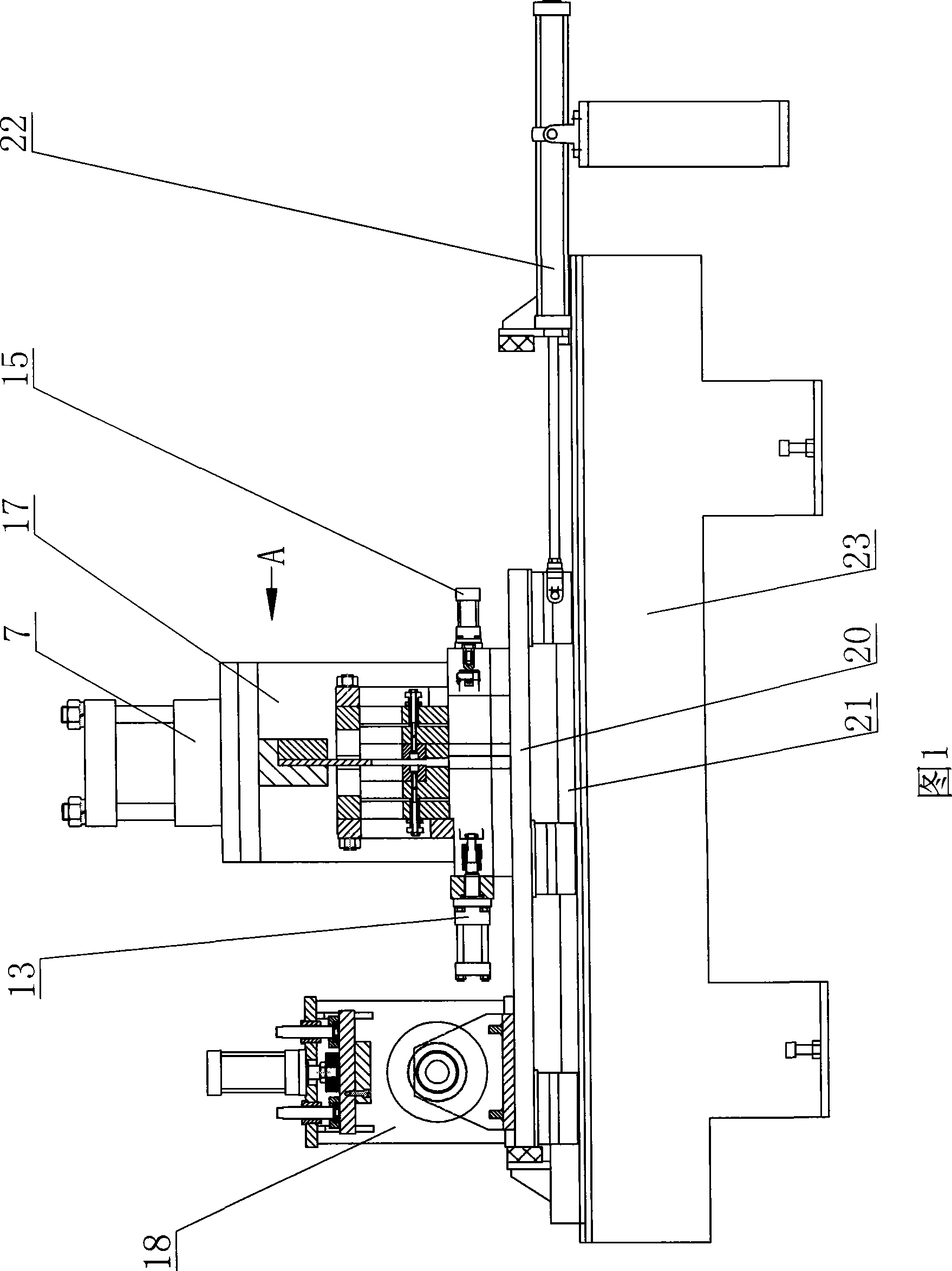
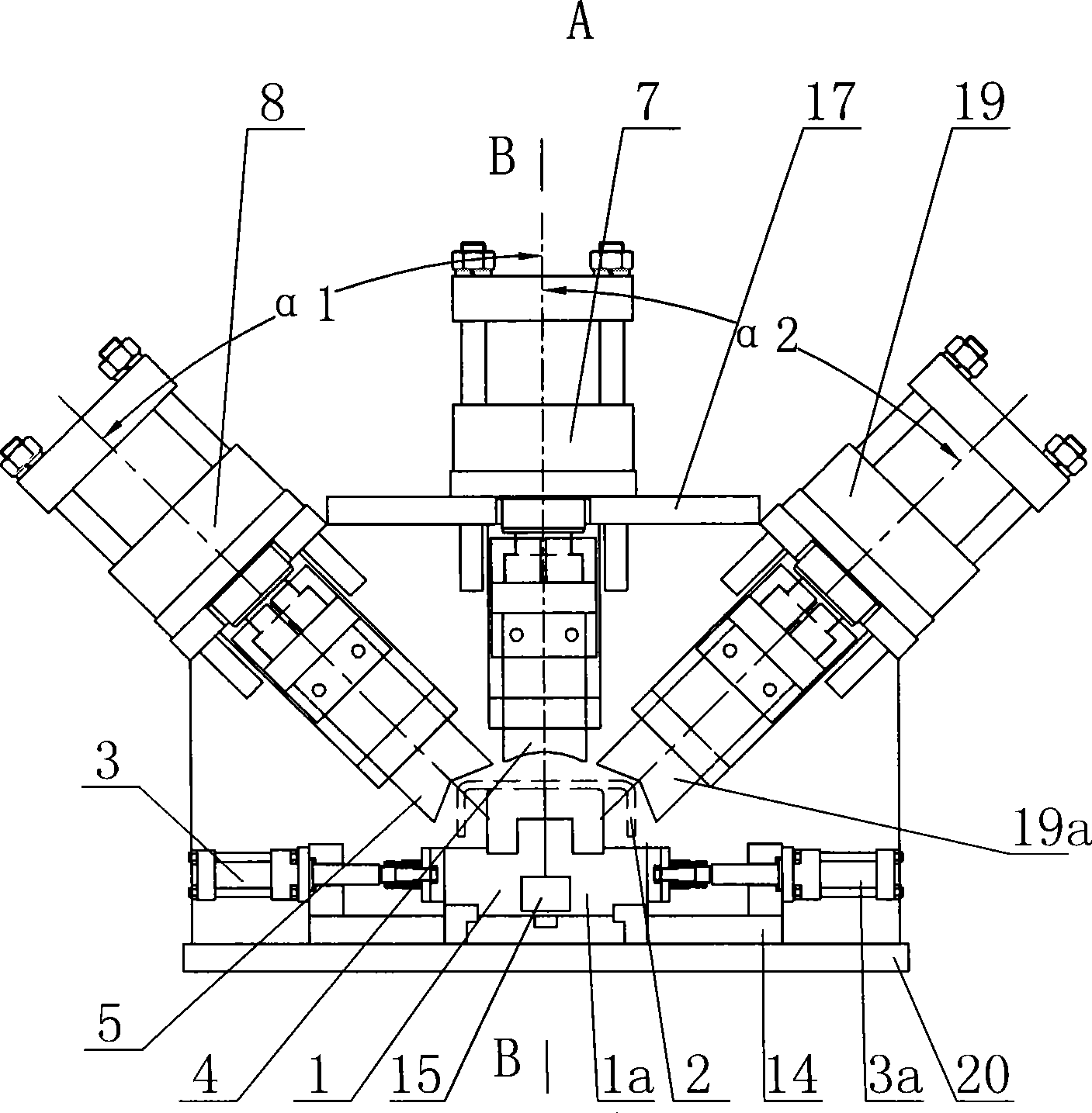
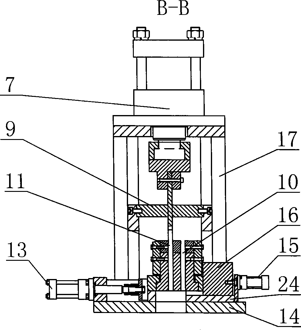

Image

  • Blanket machine
  • Blanket machine
  • Blanket machine

Examples


Embodiment Construction

[0011] The main structure of the present invention has a machine tool 23. The machine tool 23 is equipped with a clamping device 18, a tool holder and a frame 17, a vertical punching hydraulic cylinder 7 is installed on the frame 17, and a first punching knife is installed at the lower end of the vertical punching hydraulic cylinder 7 4. The first oblique punching hydraulic cylinder 8 and the second oblique punching hydraulic cylinder 19, the first oblique punching hydraulic cylinder 8 and the second oblique punching hydraulic cylinder are respectively installed on both sides of the vertical punching hydraulic cylinder 7. The second punching knife 5 and the third punching knife 19a are respectively installed at the lower end of 19, the knife seat is located on the lower side of the first punching knife 4, and a knife groove is opened on the knife seat. The first punching knife 4, the second punching knife 5, and the third punching knife 19a are respectively directed to the knife s...


PUM

PropertyMeasurementUnit
Thicknessaaaaaaaaaa

Abstract

The invention discloses a piece cutter, which comprises a machine tool, wherein the machine tool is provided with a holding fixture, a tool apron and a stander; the stander is provided with a vertical cutting hydraulic cylinder; the lower end of the vertical cutting hydraulic cylinder is provided with a first punch knife; two sides of the vertical cutting hydraulic cylinder are provided with a first obliquely arranged cutting hydraulic cylinder and a second obliquely arranged cutting hydraulic cylinder respectively; lower end of the first obliquely arranged cutting hydraulic cylinder and the second obliquely arranged cutting hydraulic cylinder are provided with a second punch knife and a third punch knife respectively; and the tool apron is positioned on the lower side of the first punch knife and is provided with a tool groove. The piece cutter has the advantages that the piece cutter greatly improves quality of shearing area and punch efficiency; U-shaped beams after the punching need no straightening procedure and can be directly used in the next procedure; the movable tool apron is arranged, can be quickly adjusted according to models of the U-shaped beams, and can punch various models of U-shaped beams; and the piece cutter can perform following-up cutting to realize continuous operation of production lines, has good punching effect, reasonable structure and low noise, and meets the requirements of national environment protection.

Description

Technical field [0001] The invention relates to the field of punching machine devices, in particular to a punching machine provided with three punching knives. Background technique [0002] With the rapid development of the heavy-duty vehicle industry and the enhancement of safety awareness, the technical requirements for the design, manufacture and installation of "U" beam products are getting higher and higher. In the production process of "U" beams, the existing technological processes and configurations have matured day by day, such as uncoiling, leveling, roll forming and other production processes are already very mature, only there are many cut-to-length methods for the finished product after roll forming. problem. The existing "U" beam cutting methods generally include sawing, single-pole vertical cutting of the model, and so on. The biggest disadvantage of the above methods is that the quality of the shear section of the automobile longitudinal beam is poor, and it is ea...

Claims


Application Information

Patent Timeline
IPC IPC(8): B23D27/00B23D35/00B23D23/00
Inventor 刘玉章
Owner JINAN CASTING FORGING MACHINERY INST
Learn More