
Cutting tip

A technology of cutting inserts and cutting devices, applied in the field of cutting inserts, can solve the problems of difficulty in making cutting inserts, the optimal particle size and optimal mixing amount of resin particles are not clear, and achieve a good cutting effect.

Active Publication Date: 2012-07-25
DISCO CORP
View PDF1 Cites 0 Cited by
  • Summary
  • Abstract
  • Description
  • Claims
  • Application Information

AI Technical Summary

Problems solved by technology

[0008] The electrodeposited abrasive tool disclosed in Patent Document 1 simply discloses a structure in which resin particles are dispersed in a plating layer holding diamond abrasive grains, but the optimal particle size and optimum compounding amount of resin particles are not clear, and there are Such a problem: According to the disclosure in Patent Document 1, it is difficult to manufacture a cutting insert capable of obtaining a good cutting result with a thin cutting edge for cutting

Method used


Image

  • Cutting tip
  • Cutting tip
  • Cutting tip

Examples


Embodiment Construction

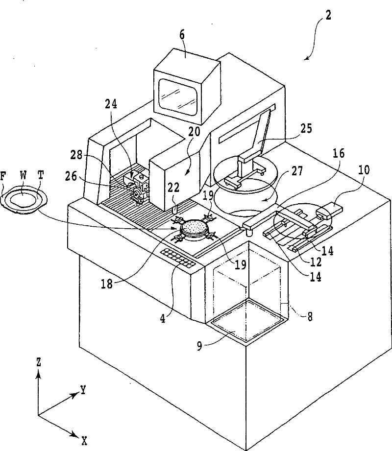
[0025] Hereinafter, embodiments of the present invention will be described in detail with reference to the drawings. figure 1 The appearance of a dicing device (cutting device) 2 suitable for mounting the cutting blade of the present invention is shown, which can cut a ceramic wafer or the like of a difficult-to-cut material to be divided into individual chips (devices).

[0026] On the front surface side of the cutting device 2, an operating member 4 for allowing an operator to input instructions to the device such as machining conditions is provided. A display unit 6 such as a CRT is provided on the upper part of the device, and the display unit 6 displays a guidance screen for an operator and an image captured by an imaging unit described later.

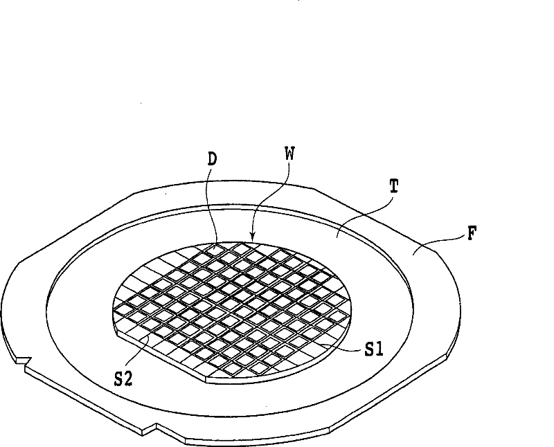
[0027] Such as figure 2 As shown, on the surface of the wafer W as the object of cutting, the first partition S1 and the second partition S2 are formed orthogonally, and the wafer W is divided by the first partition S1 and the s...


PUM

PropertyMeasurementUnit
particle diameteraaaaaaaaaa
thicknessaaaaaaaaaa

Abstract

The invention provides a tool blade, which can cut such materials difficult to be cut as a glass substrate, a ceramic substrate and the like. The tool blade is used for a cutting device, and the cutting device comprises a chuck worktable which maintains objects being processed, and a cutting component which supports the tool blade in a way that the tool blade can rotate, wherein, the tool blade cuts the objects processed and maintained on the chuck worktable. The tool blade is characterized in that the tool blade is provided with a cutting edge formed by an electro-deposition lapping tool, the cutting edge consists of superhard grinding particles, fluoride resin particles and a nickel-electro deposition layer, wherein, the superhard grinding particles are selected from a combination consisting of natural or synthesized diamond grains and cubic crystal boron nitride grinding particles, the nickel-electro deposition layer is formed by mixing and fixing the superhard grinding particles and the fluoride resin particles, the particle size of the fluoride resin particle is within the range of 0.2-20 Mum, the eutectoid content of the fluoride resin particle is within the range of 10 volume percent to 45 volume percent, and the concentration ratio of the superhard grinding particle is within the range of 60-150.

Description

technical field [0001] The invention relates to a cutting blade suitable for cutting difficult-to-cut materials such as glass and ceramics. Background technique [0002] Regarding the cutting device (cutting device), a flange is installed on the front end of the main shaft, and a cutting blade with a thin cutting edge is mounted on the flange and fixed with a nut. This cutting device is used in a field where an IC (Integrated Circuit : integrated circuit) or LSI (Large Scale Integration: Large Scale Integrated Circuit) and other silicon wafers, ceramic substrates such as lithium niobate (LN) on which optical waveguides are formed, resin substrates, glass plates, etc., are cut and divided into individual LSI chips, electronic devices or optical devices. [0003] Cutting blades used in cutting devices are roughly divided into two categories, one of which is called a hub blade, which is constructed by electrodepositing a cutting edge on the outer periphery of a circular base w...

Claims


Application Information

Patent Timeline
Patent Type & Authority Patents(China)
IPC IPC(8): B28D1/24
Inventor 新田祐士
Owner DISCO CORP
Learn More