Beam enlarging lens

A technology of beam expander and lens barrel, applied in the field of beam expander, can solve the problems of difficult to guarantee accuracy and inconvenient use, and achieve the effect of ensuring accuracy and simplifying operation

Inactive Publication Date: 2009-05-20
王国力 +1
View PDF0 Cites 4 Cited by
  • Summary
  • Abstract
  • Description
  • Claims
  • Application Information

AI Technical Summary

Problems solved by technology

For adjustable beam expanders, the lens position is usually judged by visual scales to realize magnification conversion and divergence adjustment. The accuracy is difficult to guarantee and it is inconvenient to use.

Method used


Image

  • Beam enlarging lens
  • Beam enlarging lens

Examples


Embodiment 1

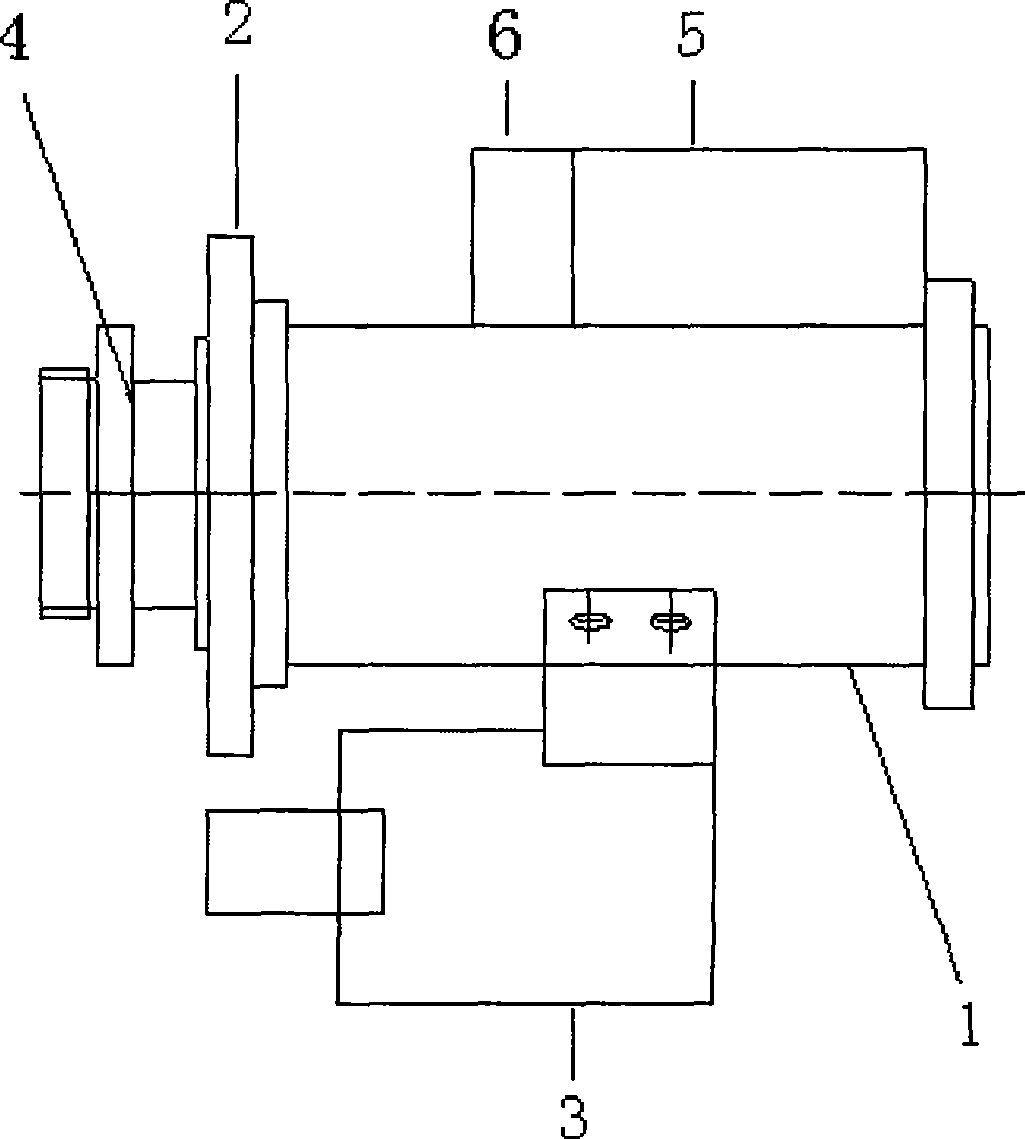
[0010] Such as figure 1 As shown, the fixed magnification beam expander includes a movable lens barrel 1, an adjusting ring 2, a fixed lens holder 4, a displacement sensor 3, a digital-to-analog conversion circuit 6 and a digital tube 5 connected to each other. The fixed magnification beam expander uses 2 groups of lenses, wherein the front group lens is fixed in the fixed lens holder 4, and the rear group lens is fixed in the movable lens barrel 1 and can be moved. The displacement sensor 3 is a variable resistor, which is installed on the moving lens barrel 1. The rotating end of the variable resistor is connected to the adjustment ring 2 through a mechanical connection device. The mechanical connection device can be a gear or chain connection. When the adjustment ring 2 is adjusted, The rotating end of the variable resistor also rotates, so that its resistance changes, and the output voltage signal also changes synchronously. These signal changes are converted into correspondi...

Embodiment 2

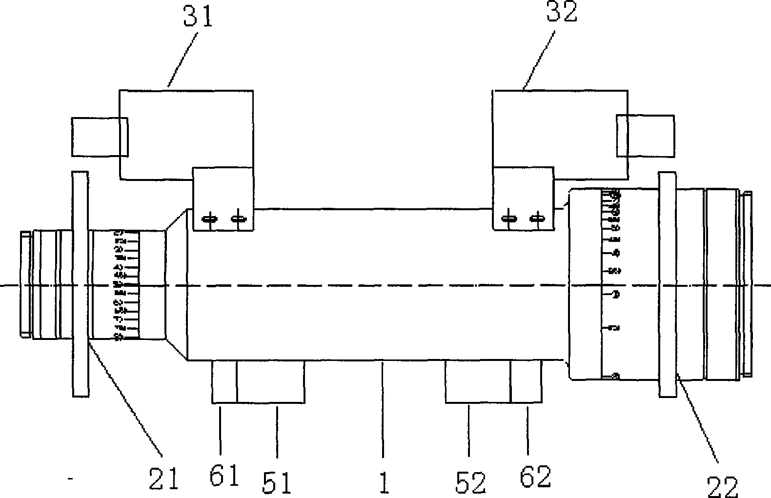
[0012] Such as figure 2 As shown, the variable magnification beam expander includes a fixed lens barrel 1, a movable lens barrel, a displacement sensor, a digital-to-analog conversion circuit and a liquid crystal display device. The movable lens barrel includes a front movable lens barrel 21 and a rear movable lens barrel 22. The displacement sensor includes a front displacement sensor 31 and a rear displacement sensor 32. The digital-to-analog conversion circuit and the liquid crystal display device include a front digital-to-analog conversion circuit 61 and a front liquid crystal display device 51. , The rear digital-to-analog conversion circuit 62 and the rear liquid crystal display device 52. The variable magnification beam expander uses 3 groups of lenses, of which the front and rear two groups of lenses are respectively fixed in the front and rear moving barrels and can be moved, and the middle group lens is fixed in the barrel 1. The front displacement sensor 31 and the rea...


PUM


Abstract

The invention relates to a beam expanding lens, which can ensure precision of regulating ratio and divergence and has convenient use. The beam expanding lens comprises a movable lens barrel and an adjusting ring, wherein a lens is fixed in the movable lens barrel. The beam expanding lens also comprises a displacement sensor, a digital-analog converter circuit, a nixietube or a liquid crystal display device which are connected in sequence, wherein the displacement sensor is connected with the movable lens barrel so as to induce information of a lens displacing along an optical axis of the lens; and the displacement sensor can be a variable resistor, a variable inductor, a photoelectric transducer or a magnetic Hall element. In the invention, position information of the lens is transferred to the digital-analog converter circuit by the displacement sensor, a corresponding position of the lens is displayed precisely by the nixietube or the liquid crystal screen, and visual scale is replaced by digital display technology, thereby operation simplification is realized, precision of the regulating ratio and the divergence is ensured. The beam expanding lens is applicable to both a fixed-power beam expanding lens and a variable power beam expanding lens.

Description

Technical field [0001] The invention relates to a beam expander, in particular to a beam expander capable of changing magnification or adjusting divergence, which is used in the fields of laser processing, laser collimation and the like. Background technique [0002] Now the types of beam expanders are different, including fixed beam expanders and adjustable beam expanders. For adjustable beam expanders, the lens position is usually judged through the visual scale to achieve magnification conversion and divergence adjustment, which is difficult to ensure accuracy and inconvenient to use. Summary of the invention [0003] The invention provides a beam expander, which can ensure the accuracy of adjusting magnification and divergence, and is convenient to use. [0004] The beam expander includes a movable lens barrel and an adjusting ring. A lens is fixed in the movable lens barrel. It also includes a displacement sensor, a digital-to-analog conversion circuit, and a digital tube o...

Claims


Application Information

Patent Timeline
Patent Type & Authority Applications(China)
IPC IPC(8): G02B7/04G01B7/02
Inventor 王国力吴玉堂
Owner 王国力
Why Eureka
Try Eureka