Backlight source of liquid crystal display

A liquid crystal display and backlight technology, which is applied to instruments, optics, light guides, etc., can solve problems such as affecting the overall thickness of the module, and achieve the effects of convenient assembly, reducing the width of the forehead and improving the utilization efficiency.

Inactive Publication Date: 2009-05-20
SHANGHAI AVIC OPTOELECTRONICS
View PDF0 Cites 11 Cited by
  • Summary
  • Abstract
  • Description
  • Claims
  • Application Information

AI Technical Summary

Problems solved by technology

However, this also affects the

Method used


Image

  • Backlight source of liquid crystal display
  • Backlight source of liquid crystal display
  • Backlight source of liquid crystal display

Examples


Example Embodiment

[0019] Example 1

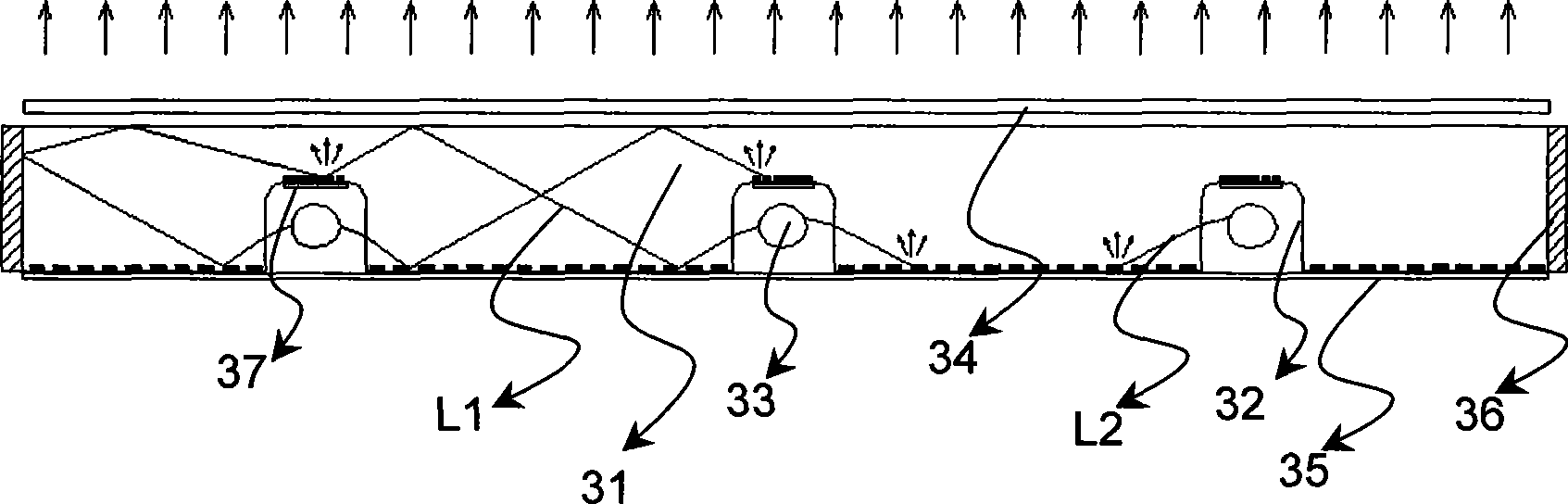
[0020] image 3 Shown is a cross-sectional view of the first backlight model of the present invention. The structure of this model consists of a light guide plate 31, a light source 33, a reflective film 35, a side reflective film 36 and a diffusion film 34. The light guide plate 31 is a specially shaped light guide plate, the light source 33 is placed in the slot 32, and side reflection films 36 are attached to both sides of the light guide plate 31. According to the needs of brightness, select the number of light sources and the number of corresponding light guide plate notches. In order to prevent bright lines from appearing in the area directly above the light source 33, a notch reflective film 37 is attached to the groove on the notch 32 for light shielding treatment. The reflection pattern of the light guide plate 31 is provided on the bottom surface of the light guide plate 31 and the bottom surface of the notch 32. The light L2 enters the light guide pl...

Example Embodiment

[0024] Example 2

[0025] Figure 6 What is shown is a cross-sectional view of another backlight source model of the present invention, which combines the structural characteristics of an edge type backlight source and a direct type backlight source. The structure of this model is composed of a light guide plate 31, a light source 33, a reflective film 35, a light source reflective cover 66, and a diffusion film 34. The light guide plate 31 is a specially shaped light guide plate, a part of the light source 33 is placed at the slot 32, and both sides of the light guide plate 31 are also installed with lamp tubes as the light source 33. According to the needs of brightness, the number of light sources 33 and the corresponding number of notches on the light guide plate are selected. In order to prevent bright lines from appearing in the area directly above the light source 33, a notch reflective film 37 is attached to the groove on the notch 32 for light shielding treatment. The ref...


PUM


Abstract

The invention provides a backlight source of a liquid crystal display. The backlight source can effectively utilize light and avoid using an expensive optical brightening film and has a simple structure and convenient assembly. In order to realize the aim, the backlight source adopts the following technical proposal: the backlight source of the liquid crystal display comprises a light guide plate, light sources, reflecting films, rabbets and a diffusion film; the bottom of the light guide plate is stuck with the reflecting films and is provided with a plurality of the rabbets; the light sources are arranged in the rabbets; the top parts of the rabbets are provided with the notch reflecting films; and the top part of the light guide plate is provided with the diffusion film. The technical proposal improves the utilization efficiency of light, greatly reduces energy consumption of LCD, reduces the whole thickness of a backlight source module in order that a high-brightness thin backlight source becomes possible and further reduces the width of the front edge of the backlight module.

Description

technical field [0001] The present invention relates to a color liquid crystal display device, and further relates to a backlight source device used in the liquid crystal display device. Background technique [0002] At present, there are mainly two types of backlight sources used for liquid crystal displays: edge type and direct type. The edge type backlight has the advantages of fewer lamp tubes, thinner, high light output efficiency, and low power consumption. figure 1 is a cross-sectional view of an edge-type backlight. like figure 1 As shown, the general edge-type backlight consists of a lamp tube 13, a reflector 14 (with a reflective film on the inner wall), a light guide plate 11 (with a reflective pattern printed on the lower surface), a reflective film 12, a diffuser film 15 and an optical brightening Diaphragm 16 etc. are formed. Part of the light emitted by the lamp tube directly enters the light guide plate, and part of the light enters the light guide plate ...

Claims


Application Information

Patent Timeline
IPC IPC(8): G02F1/13357F21V21/00G02B6/00G02B1/10F21V3/02G02F1/1335
Inventor 徐朝毅丁渊
Owner SHANGHAI AVIC OPTOELECTRONICS
Why Eureka
Try Eureka