Wide range voltage regulating circuit and implementing method of wide range voltage regulating

A technology of voltage regulation circuit and implementation method, which is applied in the direction of adjusting electrical variables, control/regulation systems, instruments, etc., and can solve the difficulty in selecting power devices such as magnetic core devices and switch tubes, difficulty in control loop design, and large inductance and other problems to achieve the effect of avoiding bus voltage drop, simple design, and easy stability of the system

Active Publication Date: 2009-05-20
SHENZHEN MINDRAY BIO MEDICAL ELECTRONICS CO LTD +1
View PDF0 Cites 13 Cited by
  • Summary
  • Abstract
  • Description
  • Claims
  • Application Information

AI Technical Summary

Problems solved by technology

[0006] 1. Control loop design is difficult
Because the input voltage is fixed, it is very difficult to ensure the stability of the system under all output voltage and load conditions when the output voltage and load range are very large.
[0007] 2. It is difficult to select power devices such as magnetic core devices and switch tubes
if used figure 1 and figure 2 In the scheme, the high current at low voltage and the high voltage at high voltage require some power devices ( figure 1 Middle MOS tubes D and C, figure 2 Middle Q12 and D12) must meet high current and high voltage at the same time, selection is difficult
In addition, the wire diameter of the inductor must not only meet the high current at low-voltage output, but also must have a large inductance to avoid saturation at high-voltage output, so the volume of the inductor is relatively large

Method used


Image

  • Wide range voltage regulating circuit and implementing method of wide range voltage regulating
  • Wide range voltage regulating circuit and implementing method of wide range voltage regulating
  • Wide range voltage regulating circuit and implementing method of wide range voltage regulating

Examples


Embodiment Construction

[0028] The present invention will be described in further detail below through specific embodiments and in conjunction with the accompanying drawings.

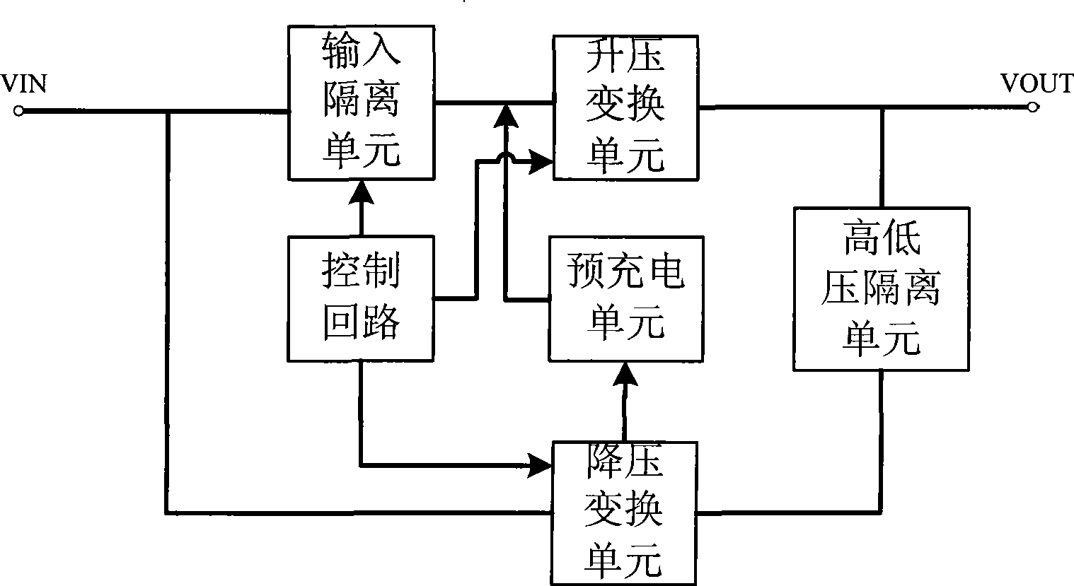
[0029] Please refer to image 3 The functional block diagram of this example, the wide-range voltage regulation circuit includes a control loop, a boost conversion unit, a buck conversion unit, a high and low voltage isolation unit, an input isolation unit, and a pre-charging unit; the control loop outputs control signals to connect the buck conversion converter, boost converter, and input isolation unit; the buck converter and boost converter share the bus voltage, and the input of the boost converter is isolated from the bus voltage through the input isolation unit; the output terminal of the buck converter is connected to the boost converter The output terminal of the step-down converter is connected through the high-voltage isolation unit; the buck converter also has a second output terminal connected to the input terminal...


PUM


Abstract

The invention discloses a wide-range voltage regulation circuit and a method for realizing wide-range voltage regulation. The circuit comprises a control circuit, a voltage reduction conversion unit and a voltage boost conversion unit, wherein the control circuit respectively outputs control signals and is connected with the voltage reduction conversion unit and the voltage boost conversion unit which share the busbar voltage; and the output end of the voltage reduction conversion unit is connected with the output end of the voltage boost conversion unit. The wide-range voltage regulation circuit and the method for realizing wide-range voltage regulation adopt the voltage reduction conversion unit to realize low-voltage section and the voltage boost conversion unit to realize high-voltage section, synthesize low-voltage output and high-voltage output into a path which is then outputted to a transmitting circuit for power supply, further realize flexible switching between a low-voltage circuit and a high-voltage circuit through boosting charge for the voltage boost conversion unit in advance, so as to avoid large impact current when the low-voltage circuit is switched to the high-voltage circuit, and avoid damage to devices or voltage sag of the busbar.

Description

【Technical field】 [0001] The invention relates to a voltage regulating circuit. 【Background technique】 [0002] Many electronic instruments and equipment have higher requirements for power supply. For example, in the ultrasonic system, there are two working modes for probe transmission, continuous wave transmission and pulse wave transmission. The voltage is low during continuous wave transmission, and the voltage is high during pulse wave transmission. Therefore, there are corresponding requirements for the power supply of the transmission circuit: output The voltage is required to be continuously adjustable in a wide range, and the load current is large when the output voltage is low, and the load current is small when the output voltage is high. In response to such requirements, there are several existing non-isolated continuously adjustable output voltage topologies, such as figure 1 and figure 2 shown. [0003] Such as figure 1 As shown, the voltage regulating cir...

Claims


Application Information

Patent Timeline
Patent Type & Authority Applications(China)
IPC IPC(8): G05F1/12
Inventor 王威李伟
Owner SHENZHEN MINDRAY BIO MEDICAL ELECTRONICS CO LTD
Why Eureka
Try Eureka