Fused joint structure in a lamp tube and forming method therefor

A technology of fusion bonding and manufacturing method, which is applied in the manufacture of discharge tubes/lamps, cold cathodes, and electrode systems. It can solve problems such as poor welding peeling and easy fracture of grain boundaries, and achieve poor deformation and stable welding strength. , The effect of reducing welding perforation defects

Active Publication Date: 2013-06-05
USHIO DENKI KK
View PDF2 Cites 0 Cited by
  • Summary
  • Abstract
  • Description
  • Claims
  • Application Information

AI Technical Summary

Problems solved by technology

[0007] However, the present inventors found that when actually welding the lead rod and the metal foil of the lamp electrode by YAG laser, as Figure 10 As shown, in metal foils such as tungsten electrodes and molybdenum foils used in lamps, often due to the energy of YAG laser welding, the welding nugget part is recrystallized, and due to the heat shrinkage after welding, it is easy to make the recrystallized part and the non-recrystallized part The grain boundary of the crystalline part is easily fractured, resulting in a very fragile weld, and poor weld peeling occurs

Method used


Image

  • Fused joint structure in a lamp tube and forming method therefor
  • Fused joint structure in a lamp tube and forming method therefor
  • Fused joint structure in a lamp tube and forming method therefor

Examples


Embodiment Construction

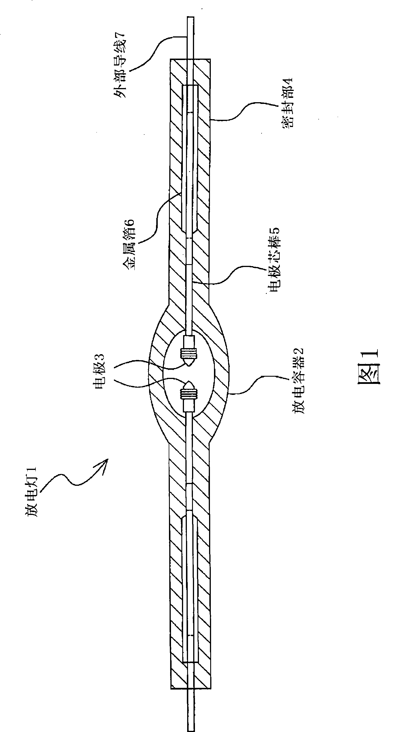
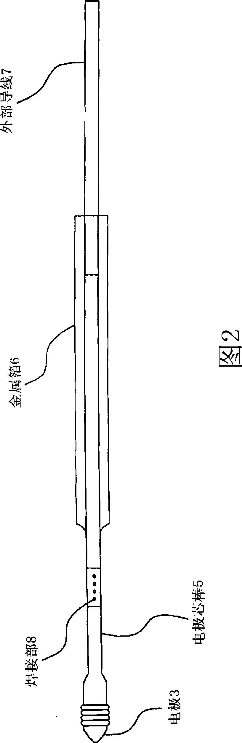
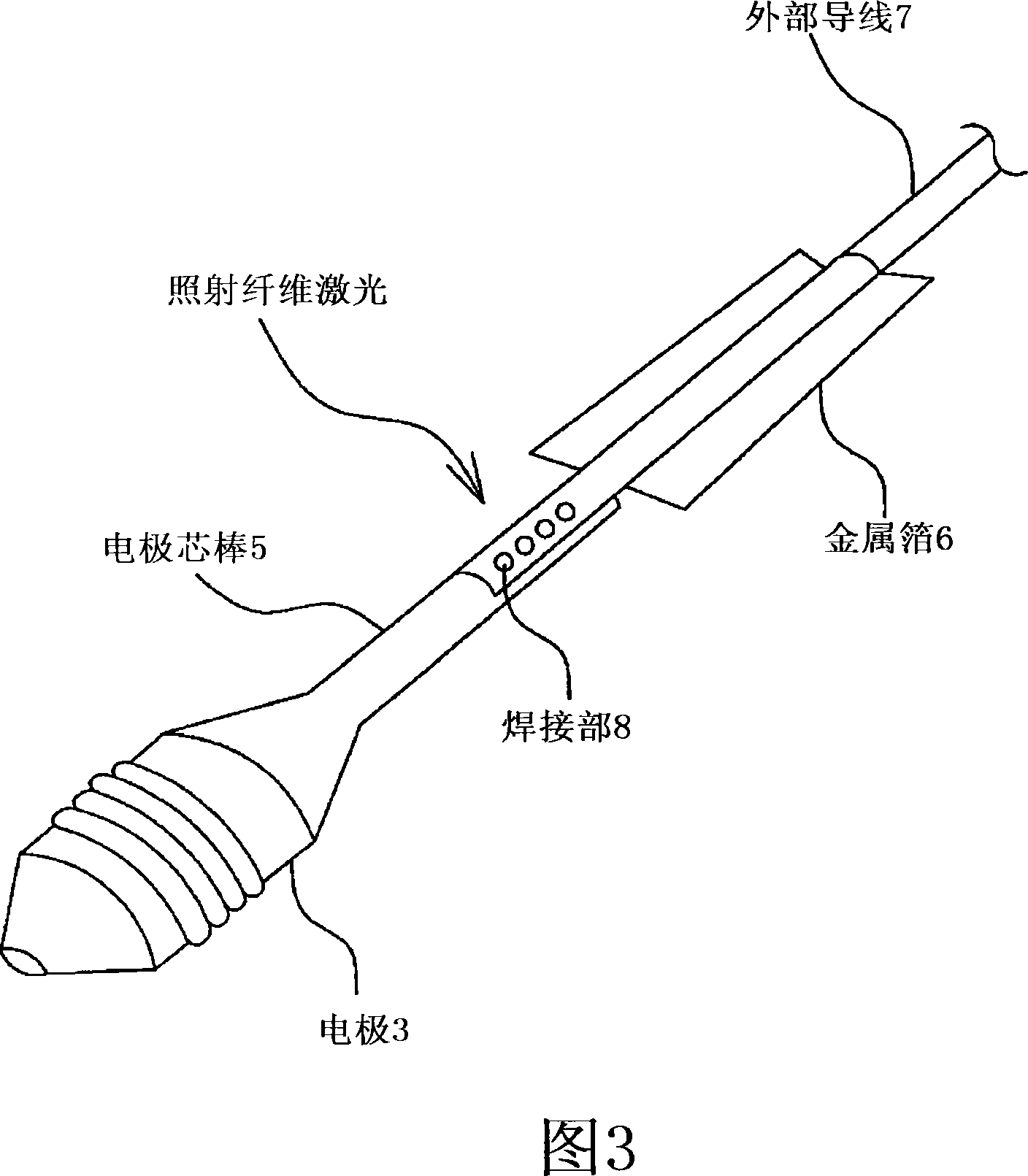
[0024] Lamps to which the fusion-bonded structure of the present invention is applied include incandescent lamps or discharge lamps typified by halogen lamps. In addition, in the present invention, "conductive member" refers to an inner lead rod and an outer lead rod in an incandescent lamp, and refers to an electrode core rod and an outer lead rod in a discharge lamp using a metal foil seal. In the discharge lamp of the foil seal, a plurality of metal foils are welded, a disk-shaped member connected to an electrode mandrel, and a disk-shaped member connected to an external lead.

[0025] refer to Figure 1 to Figure 4 The first embodiment of the present invention will be described.

[0026] figure 1 It is a cross-sectional view showing the configuration of a both-ends-sealed type discharge lamp using one metal foil seal.

[0027] As shown in the figure, a pair of electrodes 3 are disposed in the discharge vessel 2 of the discharge lamp 1, and a metal foil of an electrode ...


PUM


Abstract

A fused joint structure comprises a metallic foil; and a conductive member made of high melting point metal, wherein a concave portion is formed in the metallic foil and the conductive member on an area where the metallic foil is put together on a surface of the conductive member, and wherein a circumferential edge of the concave portion is covered with the conductive member.

Description

technical field [0001] The invention relates to a fusion bonding structure related to a lamp power supply structure and a manufacturing method thereof. Background technique [0002] Conventionally, in halogen lamps for OA, mercury lamps for liquid crystal projection light sources, and metal halide lamps for general lighting, internal leads and external leads are bonded via metal foil in the sealing part to ensure the airtightness of the light-emitting space inside the lamp. . When the internal wire and the external wire are bonded to the metal foil, for example, the OA is sealed by a pinch seal (pinch seal), and the bonding part of the metal foil and the internal wire of the halogen lamp is sealed by a shrink seal (shrink seal). Conventionally, resistance welding is used to join the metal foil and internal lead wires of mercury lamps used as light sources for projectors. [0003] However, in the resistance welding method, welding conditions fluctuate due to changes in weld...

Claims


Application Information

Patent Timeline
Patent Type & Authority Patents(China)
IPC IPC(8): H01J61/36
CPCH01J61/368H01J9/326
Inventor 长町信宏熊田丰彦
Owner USHIO DENKI KK
Why Eureka
Try Eureka