Liquid crystal display panel

A liquid crystal display panel and substrate technology, applied in static indicators, nonlinear optics, instruments, etc., to achieve the effects of increasing uniformity, saving area, and increasing availability

Inactive Publication Date: 2009-05-27
CHUNGHWA PICTURE TUBES LTD
View PDF0 Cites 36 Cited by
  • Summary
  • Abstract
  • Description
  • Claims
  • Application Information

AI Technical Summary

Problems solved by technology

[0005] The purpose of the present invention is to disclose a liquid crystal display panel, to overcome the problems existing in the existing liquid crystal display panel

Method used


Image

  • Liquid crystal display panel
  • Liquid crystal display panel
  • Liquid crystal display panel

Examples


Embodiment Construction

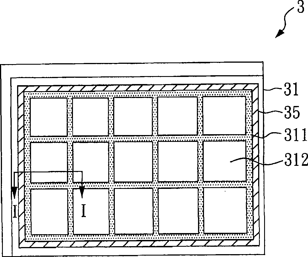
[0030] image 3 A schematic diagram of a liquid crystal display panel of a preferred embodiment of the present invention shown, Figure 4 show image 3 The schematic cross-sectional view of the liquid crystal display panel I-I line segment mark.

[0031] Please also refer to image 3 , Figure 4 , as shown in the figure, the liquid crystal display panel 3 includes: an upper substrate 31 with a support 35 , a lower substrate 32 and a liquid crystal 33 arranged between the upper substrate 31 and the lower substrate 32 .

[0032] The above-mentioned lower substrate 32 is disposed opposite to the upper substrate 31 , and it is provided with at least one pixel 321 , and the pixel 321 receives image display data to display an image.

[0033] The above-mentioned upper substrate 31 is provided with a color filter composed of a black matrix 311 and a color layer 312. The color layer 312 is set corresponding to the pixel 321, and the colors of the color layer 312 corresponding to di...


PUM


Abstract

The invention provides a liquid crystal display panel, comprising an upper base plate and a lower base plate. The upper base plate is provided with a support which is arranged at the periphery area of the upper base plate and has a groove. The lower base plate and the upper base plate are arranged oppositely. The frame glue is separated from the liquid crystal through the support on the upper base plate, thus avoiding the frame glue polluting the liquid crystal and enhancing the crystal cell clearance evenness in the process of assembling the two base plates, additionally saving the occupation of the edge area of the liquid crystal display panel and increasing the utilization ratio of the base plate.

Description

technical field [0001] The invention relates to a liquid crystal display panel, in particular to a liquid crystal display panel which can avoid contamination of liquid crystal by frame glue. Background technique [0002] Please refer to figure 1 A schematic cross-sectional view of a known liquid crystal display panel is shown. The liquid crystal display panel 1 is composed of an upper substrate 11 , a lower substrate 12 and a liquid crystal 13 . The upper substrate 11 and the lower substrate 12 are manufactured separately. After the upper substrate 11 and the lower substrate 12 are manufactured, an assembly process is required to fix the upper substrate 11 and the lower substrate 12 . A known method is to fill the lower substrate 12 with liquid crystals 13 , and apply sealant 14 on the edge of the upper substrate 11 , and align the upper substrate 11 and the lower substrate 12 . Then, it is irradiated with ultraviolet light to harden the sealant 14 to fix the upper substr...

Claims


Application Information

Patent Timeline
Patent Type & Authority Applications(China)
IPC IPC(8): G02F1/1333G02F1/1339G02F1/1362G02F1/133
Inventor 廖建达邱献清
Owner CHUNGHWA PICTURE TUBES LTD
Why Eureka
Try Eureka