Small-sized unmanned aerial vehicle automatic landing leveling control method and apparatus

A technology of a small unmanned aerial vehicle and a control method, which is applied in non-electric variable control, position/direction control, control/regulation system and other directions, can solve the problem that the speed of the unmanned aerial vehicle is small, cannot provide information that meets the lifting speed and acceleration information, low altitude

Inactive Publication Date: 2009-05-27
BEIHANG UNIV
View PDF0 Cites 36 Cited by
  • Summary
  • Abstract
  • Description
  • Claims
  • Application Information

AI Technical Summary

Problems solved by technology

[0007] For small UAVs with simple sensor configurations, in order to reduce costs, the system composition will be relatively simple, generally only equipped with altitude sensors, airspeed sensors, pitch angle and pitch rate sensors that meet basic measurement requirements, such as atmospheric engines and gyro components , and will not be equipped with a radio altimeter specially used for automatic take-off and landing control, let alone expensive equipment such as inertial navigation, so the UAV with simple sensor configuration cannot provide the lifting required to meet the general automatic leveling control structure Velocity information and lifting acceleration information, the general automatic leveling control method is not suitable for automatic landing of small UAVs with simple configuration
[0008] In addition, considering that during the take-off and landing phases, the speed of the UAV is relatively small and the altitude is relatively low, the change of airflow (mainly wind) has a very obvious impact on the flight of the UAV, and the error of the sensor in the control system is to make the control Another important reason for deviation, the influence of these uncertain factors will make the effect of automatic control not so ideal

Method used


Image

  • Small-sized unmanned aerial vehicle automatic landing leveling control method and apparatus
  • Small-sized unmanned aerial vehicle automatic landing leveling control method and apparatus
  • Small-sized unmanned aerial vehicle automatic landing leveling control method and apparatus

Examples


Embodiment Construction

[0049] The UAV automatic landing leveling control method of the present invention will be further described below in conjunction with the accompanying drawings and examples.

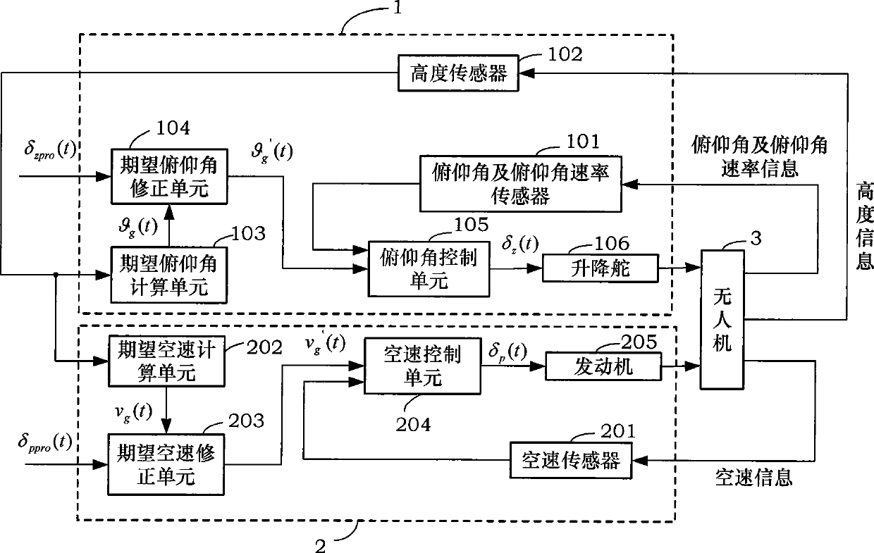
[0050] Such as image 3 As shown, the control device designed in the control method for automatic landing and leveling of small UAVs provided by the present invention is composed of two control modules, the pitch angle control loop 1 and the airspeed control loop 2 .

[0051] Among them, the pitch angle control loop 1 is composed of a pitch angle and pitch angle rate sensor 101 , a height sensor 102 , a desired pitch angle calculation unit 103 , a desired pitch angle correction unit 104 , a pitch angle control unit 105 and an elevator 106 . The expected pitch angle calculation unit 103 calculates the expected pitch angle according to the height information of the unmanned aerial vehicle 3 collected by the height sensor 102 The desired pitch angle and the amount of elevator stick δ zpro (t) Correspondi...


PUM


Abstract

The invention discloses a method and a device for automatic landing leveling control of a small unmanned aerial vehicle. The landing leveling control device consists of a pitch attitude control circuit and an airspeed control circuit. Aiming at the problem that unmanned air vehicle with a simple sensor can not acquire vertical speed information and vertical acceleration speed information with required precision, the method and the device make full use of an available sensor information and calculate an expected pitch attitude g(t), an expected pitch attitude g'(t) containing correction, an expected airspeed vg(t), an expected airspeed vg'(t) containing correction, elevator control command delta Z(t), an engine chock valve command delta(t) and so on to realize control procedures in the control circuits and achieve the aim of automatic landing leveling control. Meanwhile, remote control operating personnel can operate an operating lever of an elevator and an operating lever of a chock valve in a leveling process according practical situation and carry out correction control of automatic leveling, thereby effectively improves the anti-interference capacity and landing precision of an airplane.

Description

technical field [0001] The invention belongs to the field of flight control of unmanned aerial vehicles, and specifically refers to a small unmanned aerial vehicle automatic landing leveling control method and device thereof with simple sensor configuration. Background technique [0002] During the landing approach process, the wheeled take-off and landing UAV must accurately track the desired landing trajectory to safely and reliably touch down at the desired landing point and complete the landing control. Automatic leveling control is a key stage in the autonomous landing process of wheeled take-off and landing UAVs. Whether the leveling control is accurate, safe and reliable directly affects the accuracy and safety of aircraft landing. [0003] The sliding and landing process of a general wheeled take-off and landing UAV includes stages such as height setting, sliding, leveling, falling and landing, such as figure 1 shown. Before landing, the aircraft first flies at a f...

Claims


Application Information

Patent Timeline
Patent Type & Authority Applications(China)
IPC IPC(8): G05D1/00
Inventor 王英勋王宏伦张翠萍王勇方小星
Owner BEIHANG UNIV
Why Eureka
Try Eureka