Manufacturing method and manufacturing device for coil component

A coil component and manufacturing device technology, applied in coil manufacturing, transformer/inductor parts, transformer/inductor coil/winding/connection, etc., can solve the problems of roller core terminal adhesion, resin overflow, sealing, etc., to achieve Effect of reducing characteristic variation and improving characteristics

Active Publication Date: 2009-05-27
TDK CORPARATION
View PDF2 Cites 26 Cited by
  • Summary
  • Abstract
  • Description
  • Claims
  • Application Information

AI Technical Summary

Problems solved by technology

[0006] However, in the above conventional method of manufacturing a coil component, there is a problem that when the roller core is inserted into the recess, the resin in the recess overflows, and the resin adheres to parts where the resin should not adhere, such as the terminals provided on

Method used


Image

  • Manufacturing method and manufacturing device for coil component
  • Manufacturing method and manufacturing device for coil component
  • Manufacturing method and manufacturing device for coil component

Examples


Embodiment Construction

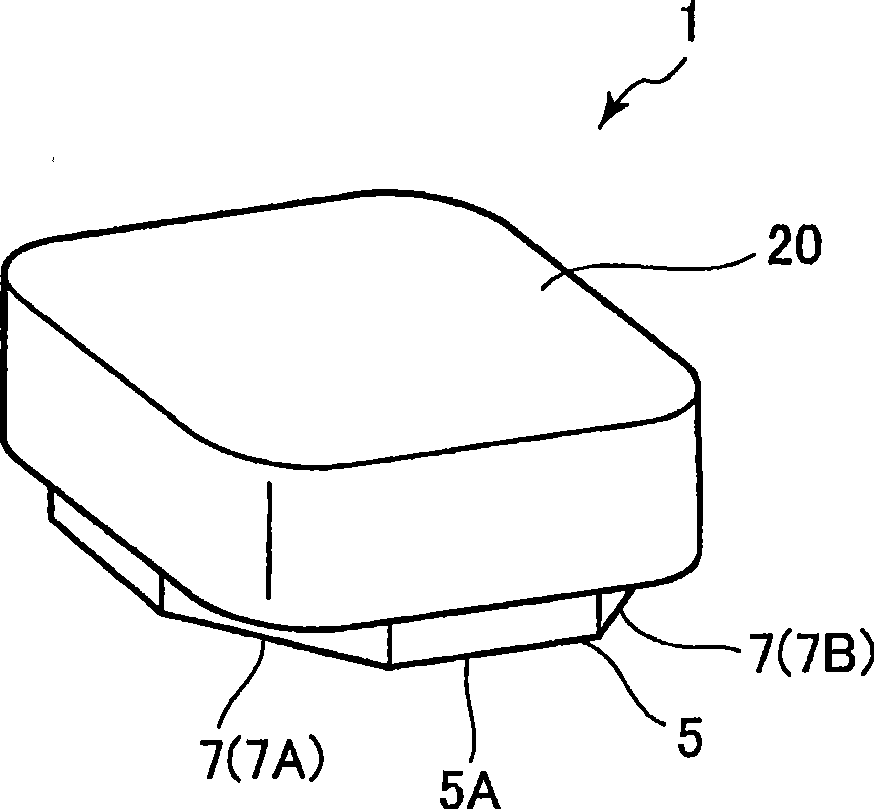
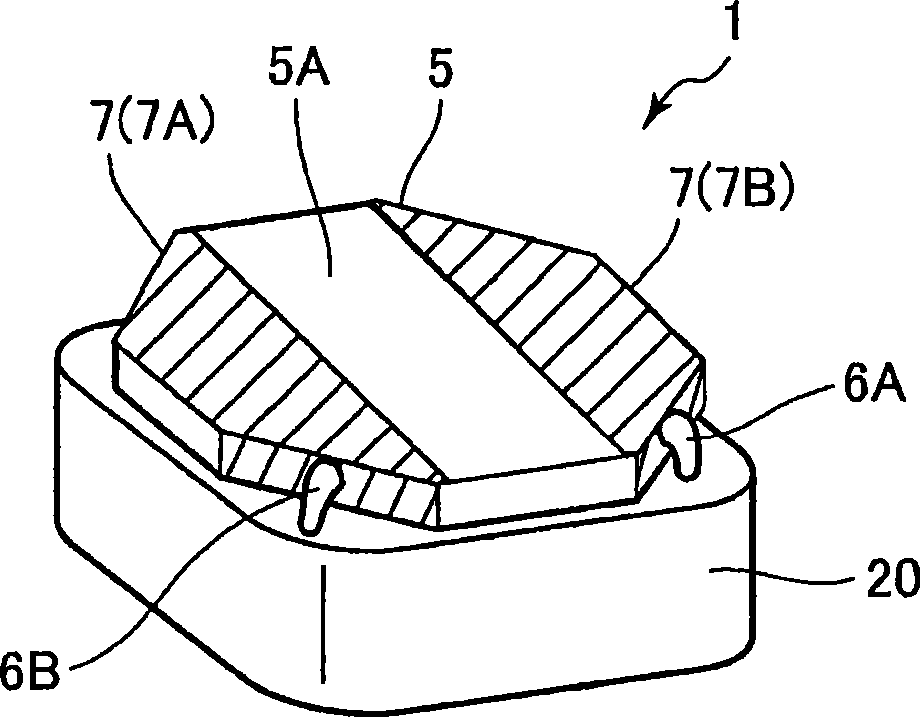
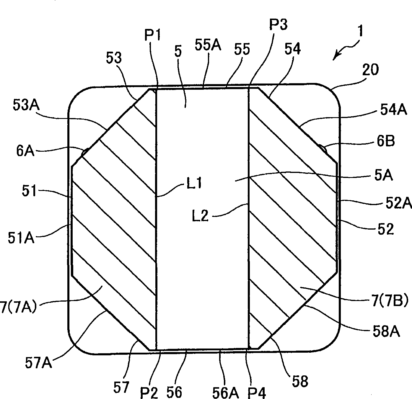
[0060] Refer below figure 1 — Figure 8 A coil component according to an embodiment of the present invention, its manufacturing method, and its manufacturing apparatus will be described. First, the coil component will be described. Coil part 1, specifically, is a kind of power system coil part, such as Figure 4 As shown, it is mainly composed of a core 2 , a winding 6 , a terminal electrode portion 7 and a resin portion 20 . The portion of the coil component 1 other than the resin portion 20 corresponds to a coil portion.

[0061] The core 2 is composed of a substantially cylindrical winding core portion 3 ( Figure 7 etc.) and a pair of first flange portion 5 and second flange portion 4 provided on both ends of the winding core portion 3. Since the first flange portion 5 and the second flange portion 4 are symmetrical in shape, unless otherwise mentioned, only the first flange portion 5 will be described, and the description of the second flange portion 4 will be omitte...


PUM


Abstract

Provided is a coil component having a core including a winding portion, and first and second flanges disposed one on either end of the winding portion, A winding is wound about the winding portion, and first and second terminal electrodes are disposed on the first flange. The first flange has an octagonal shape including a bottom surface, a first peripheral surface, first and third omitted peripheral surfaces disposed one on either side of the first peripheral surface, a second peripheral surface opposing the first peripheral surface, and second and fourth omitted peripheral surfaces disposed one on either side of the second peripheral surface. The first terminal electrode is disposed across the first omitted peripheral surface, a part of the bottom surface in a region connecting the entire first omitted side to the entire third omitted side, and the third omitted peripheral surface. The second terminal electrode is disposed across the second omitted peripheral surface, a part of the bottom surface in a region connecting the entire second omitted side to the entire fourth omitted side, and the fourth omitted peripheral surface. The winding has a first end electrically connected to the first terminal electrode on the first omitted peripheral surface and a second end electrically connected to the second terminal electrode on the second omitted peripheral surface.

Description

technical field [0001] The present invention relates to a coil component, a manufacturing method and a manufacturing device thereof, and more particularly to a power supply coil component capable of low height and high density mounting, a manufacturing method and a manufacturing device for manufacturing the power supply coil component. Background technique [0002] As a coil component, the structure which has the roll core which has a pair of flange part and the winding core part which connects this pair of flange part is known. In recent electronic devices, such as mobile phones, high-density mounting of internal devices is required as the performance increases. Therefore, in order to reduce the volume of coil components, JP 2005-210055 A lowers the height or shortens the distance between adjacent coil components. [0003] Here, when wiring the winding on the mounting surface, only the upper back of the wiring portion becomes larger. Furthermore, in the above-mentioned pu...

Claims


Application Information

Patent Timeline
IPC IPC(8): H01F27/32H01F27/28H01F41/12
CPCH01F2017/048H01F17/045H01F27/022H01F27/292H01F27/255H01F41/005Y10T29/4902
Inventor 东海林淳森田诚进藤雅俊小泽征敏
Owner TDK CORPARATION
Why Eureka
Try Eureka