

Control circuit for electromagnet of low-tension switch electric appliance
A low-voltage switch and control circuit technology, applied to circuits, relays, electrical components, etc., to achieve the effects of prolonging working life, reducing energy consumption, and reducing volume
- Summary
- Abstract
- Description
- Claims
- Application Information
AI Technical Summary
Problems solved by technology
Method used
Image

Examples
Embodiment Construction
[0014] The present invention will be described in detail below in conjunction with the accompanying drawings and embodiments.
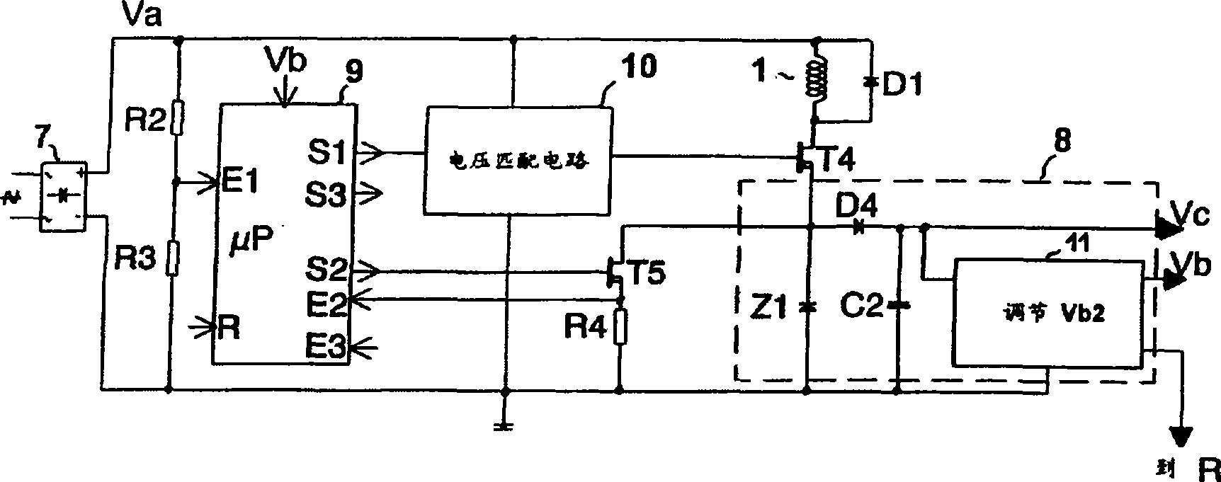
[0015] figure 1 It is the principle diagram of the electromagnet control circuit of the invention patent CN99122868 for low-voltage switching appliances. It has been explained in the background technology, and will not be repeated here.
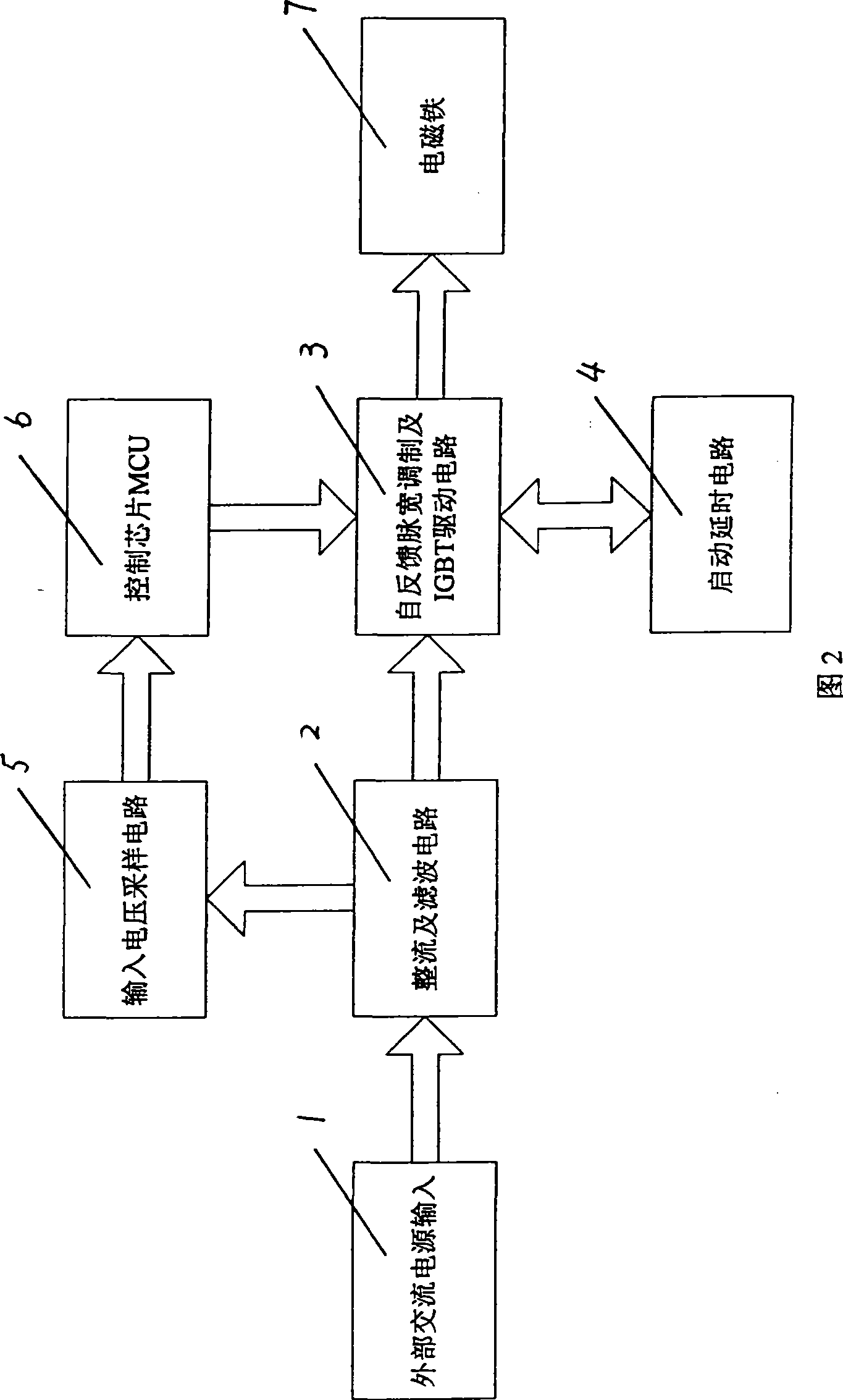
[0016] Referring to Fig. 2, this is a block diagram of the hardware principle of the electromagnet control circuit of the low-voltage switchgear of the present invention.
[0017] The electromagnet control circuit includes an external AC power input 1, a rectification filter circuit 2, a self-feedback pulse width modulation and IGBT drive circuit 3, a start-up delay circuit 4, an input voltage sampling circuit 5, a control chip circuit 6, and an electromagnet 7 .
[0018] The signal transmission between the above circuits: the external AC power input 1 is rectified and filtered by the rectification and filter circ...
PUM
 Abstract
Description
Claims
Application Information