Three-phase/biphase coordinates conversion circuit for frequency changer
A technology of coordinate transformation and frequency converter, which is applied in the output power conversion device, the conversion of AC power input to AC power output, electrical components, etc. The effect of saving resources, improving real-time processing capabilities, and improving responsiveness
- Summary
- Abstract
- Description
- Claims
- Application Information
AI Technical Summary
Problems solved by technology
Method used
Image
Examples
Embodiment Construction
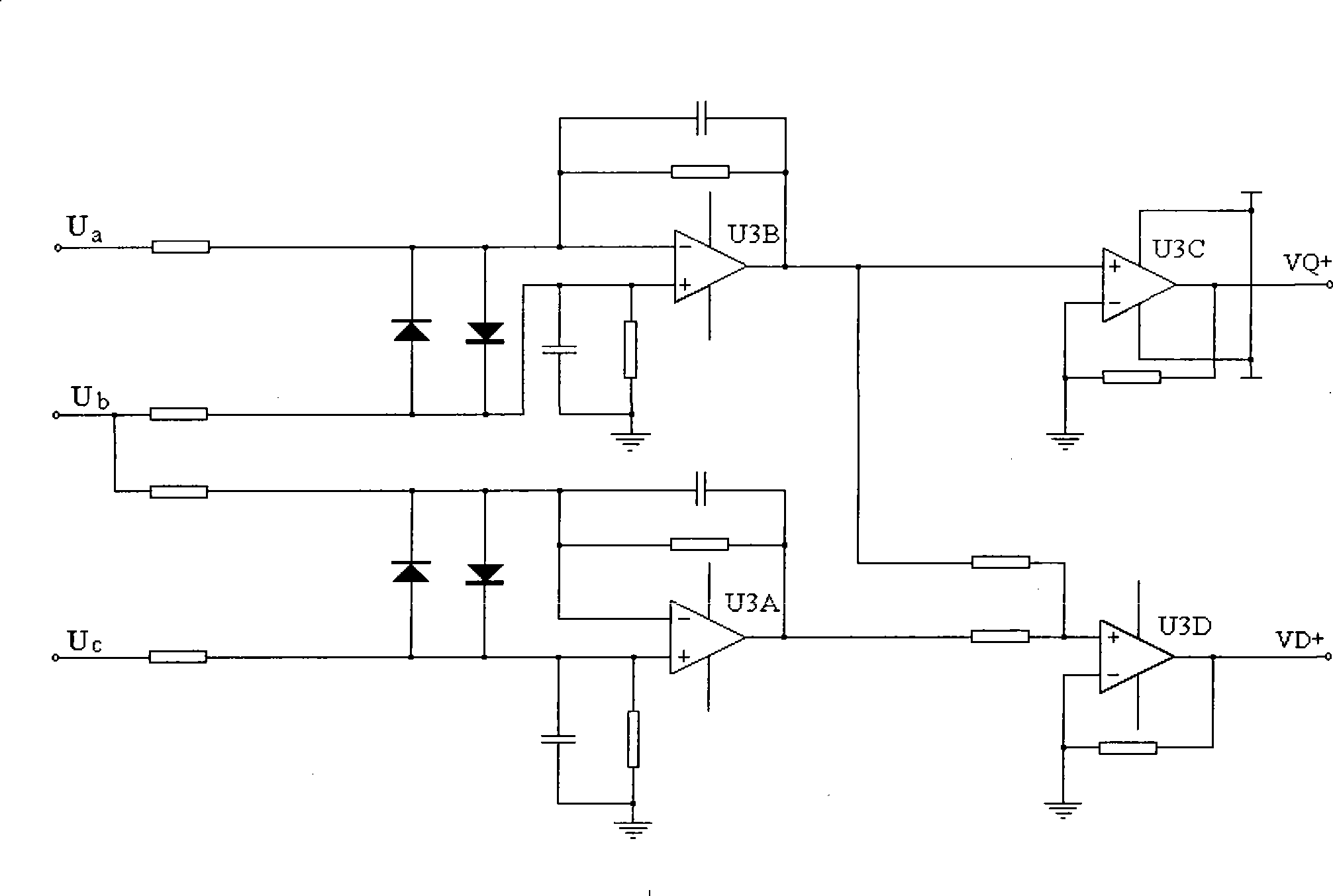
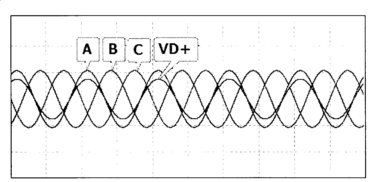
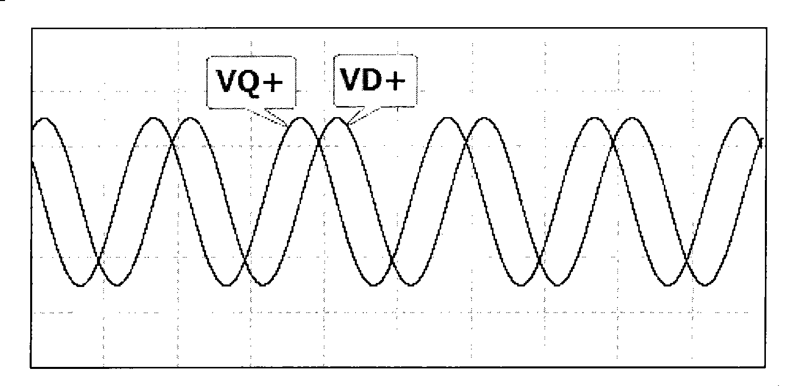
[0013] figure 1 It is the schematic diagram of the three-phase / two-phase coordinate transformation circuit of the present invention. The three-phase / two-phase coordinate transformation circuit of the present invention adopts the combination of the differential proportional operator, the same-phase proportional operator and the same-phase sum operator to complete the U under the static coordinate system. a , U b , U c The three-phase voltage signals are equivalently converted into voltage signals in the VD+ and VQ+ two-phase static coordinate system. The transformation circuit is composed of two differential proportional operators, an in-phase proportional operator and an in-phase sum operator; under the stationary coordinate system U a , U b The two-phase voltage is connected to a differential proportional calculator, and the differential proportional calculator is connected to the same-phase proportional calculator and the same-phase summation calculator; in the static co...
PUM
 Abstract
Description
Claims
Application Information
 - R&D
- Intellectual Property
- Life Sciences
- Materials
- Tech Scout
- Unparalleled Data Quality
- Higher Quality Content
- 60% Fewer Hallucinations
Browse by: Latest US Patents, China's latest patents, Technical Efficacy Thesaurus, Application Domain, Technology Topic, Popular Technical Reports.
© 2025 PatSnap. All rights reserved.Legal|Privacy policy|Modern Slavery Act Transparency Statement|Sitemap|About US| Contact US: help@patsnap.com


