
Method and strand-guiding device for guiding a cast strand

A guide device, continuous casting billet technology, applied in workpiece surface treatment equipment, metal rolling, manufacturing tools, etc., can solve problems such as dependence on cross-sectional form, improve casting speed and operating reliability, controllable, Small effect of abrasion and/or flame loss

Inactive Publication Date: 2009-05-27
SMS DEMAG AG
View PDF2 Cites 9 Cited by
  • Summary
  • Abstract
  • Description
  • Claims
  • Application Information

AI Technical Summary

Problems solved by technology

However, this measure does not completely prevent the problem of edge crack formation in the region of the strand guide, and moreover it depends too much on the cross-sectional form of the respectively cast strand

Method used


Image

  • Method and strand-guiding device for guiding a cast strand
  • Method and strand-guiding device for guiding a cast strand
  • Method and strand-guiding device for guiding a cast strand

Examples


Embodiment Construction

[0028] The present invention is described in detail below with reference to the above-mentioned drawings in the form of embodiments. The same technical features are indicated by the same reference numerals in all the drawings.

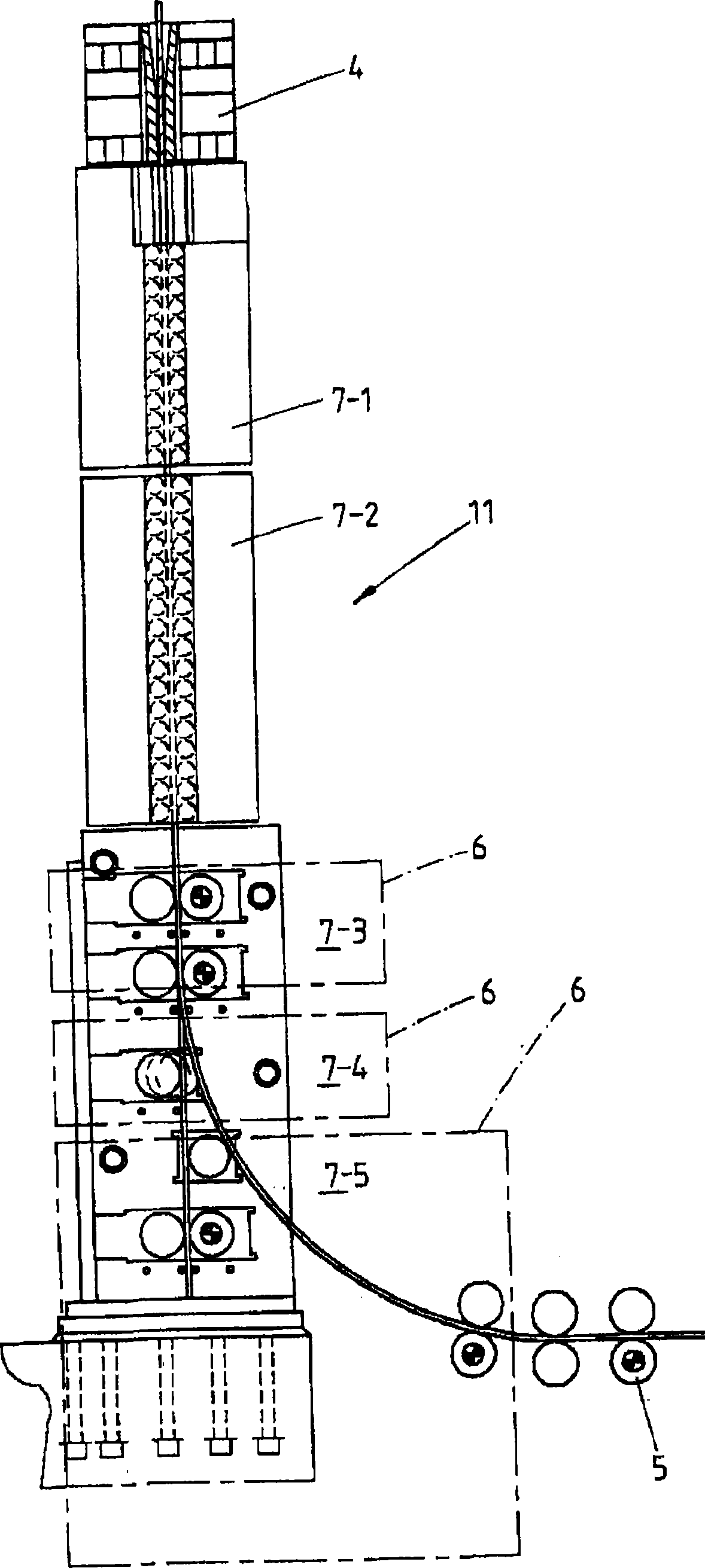
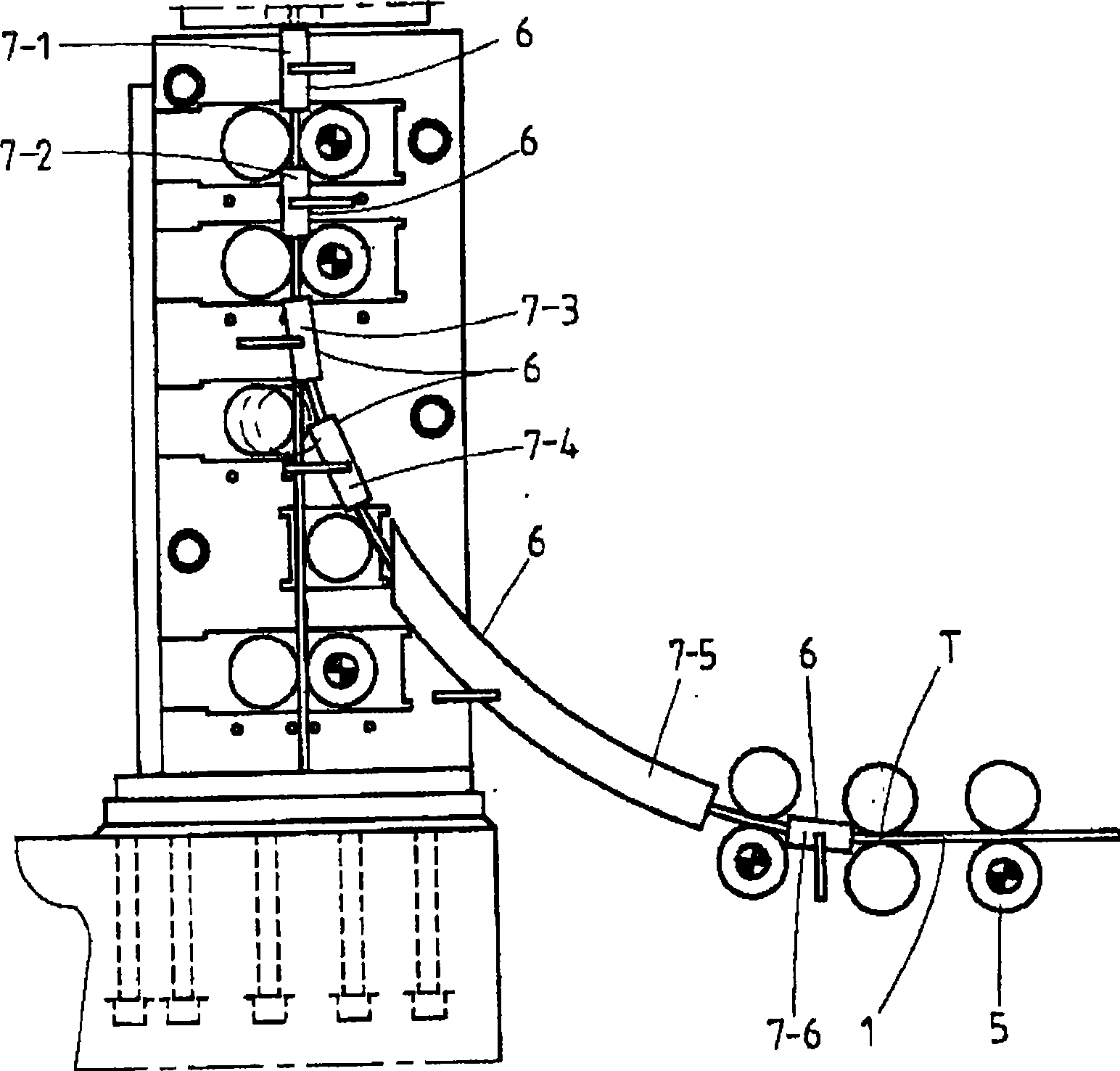
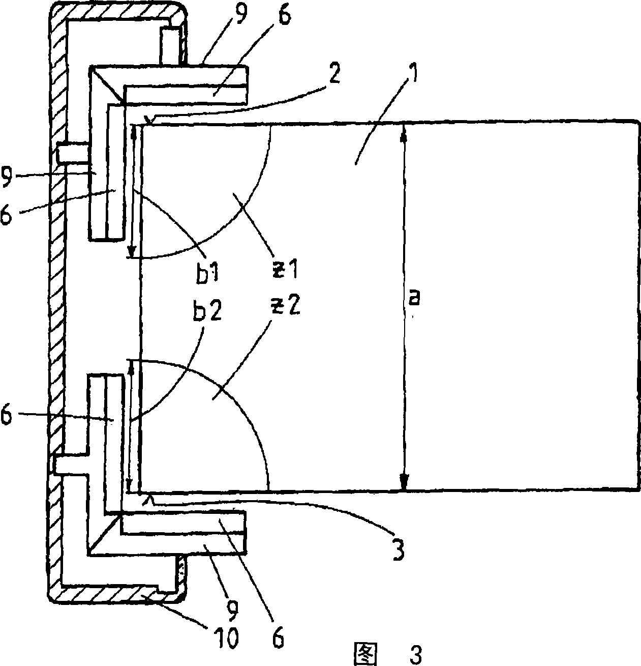
[0029] figure 1 Shown is a continuous casting machine with a mold 4 and a continuous casting slab guide 11 for supporting, guiding and annealing the continuous casting material, especially cast steel, also referred to below as the continuous casting slab 1. The continuous casting slab 1 according to the present invention is cast into a cross-sectional shape having at least edges 2, 3; see Figures 3 and Figure 4 .

[0030] according to figure 1 The edges 2, 3 on the narrow side of the continuous casting slab 1 in the area of ​​the continuous casting slab guide between the exit of the mold 4 and the correction point of the straightening drive 5 are protected by the use of a large-area porous burner area 6 Heating, especially see figure 1 with figure 2 ....


PUM


Abstract

The invention relates to a method and a strand-guiding device for guiding and regulating the temperature of a strand, in particular of steel, in sizes which have at least one edge (2, 3). In this case, the at least one edge (2, 3) is heated by supplying energy in order to avoid stress formation and / or crack formation. Provision is made according to the invention for the edges (2, 3) of the strand (1) to be heated in the strand-guiding region through the use of porous-burner zones (6).

Description

Technical field [0001] The present invention relates to a method for supporting and guiding a continuous casting slab in the form of at least edges for casting, especially for cast steel, and a continuous casting slab guiding device. In order to avoid the formation of stresses and / or cracks during deformation, at least the edges of the continuous casting slab, for example the slab, are heated by the supply of energy. [0002] In particular, the present invention relates to a method and device for the optimal temperature introduction of a continuous casting slab whose cross section is not circular or elliptical, but rectangular or polygonal. Even when the cooling medium is uniformly loaded in this form, due to the two-dimensional heat dissipation on the edges, the cooling is more intense than on the wide side of the continuous casting slab. This effect can be greatly enhanced by unsuitable or unadjustable secondary cooling. In addition, peritectic and microalloyed thick steel plate...

Claims


Application Information

Patent Timeline
Patent Type & Authority Applications(China)
IPC IPC(8): B22D11/12B21B45/00
Inventor W·韦谢德尔H·冯威尔J·施卢特U·法尔肯雷克M·贝克
Owner SMS DEMAG AG
Learn More