Friction cloth for liquid crystal panel manufacturing

A technology for liquid crystal panels and fabrics, used in textiles and papermaking, instruments, optics, etc., can solve the problems of unstable brushing, no fixed tilting method, etc.

Inactive Publication Date: 2011-12-14
SOMACHO
View PDF3 Cites 3 Cited by
  • Summary
  • Abstract
  • Description
  • Claims
  • Application Information

AI Technical Summary

Problems solved by technology

Furthermore, in the case of conventional cotton gauze, since it has not been processed with resin impregnation, only unstable napping is the only method of imparting inclination to the pile, and there is no method that can reliably fix the inclination.

Method used


Image

  • Friction cloth for liquid crystal panel manufacturing
  • Friction cloth for liquid crystal panel manufacturing
  • Friction cloth for liquid crystal panel manufacturing

Examples


Embodiment 1

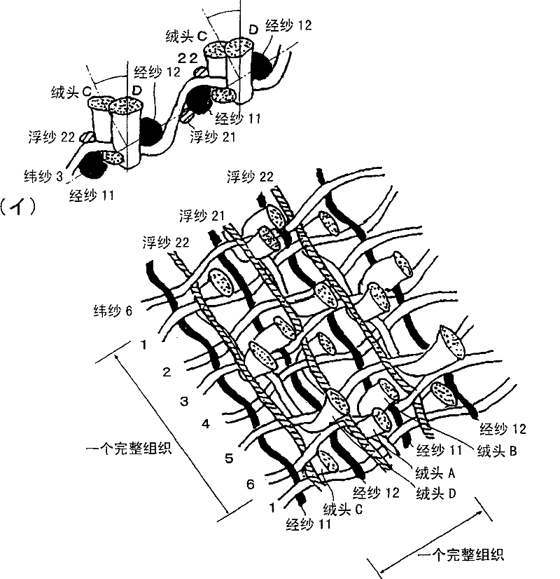
[0054] use figure 1 Trial-manufacture friction cloth with fabric structure. The results are collated in Table 1. Use cotton yarn No. 60 double-ply yarn as the ground warp yarn, use polyester 56 dtex double-ply yarn as the 5 / 1 floating yarn and the ground warp yarn of the plain weave, and the pile yarn is woven into a pile yarn with 30.6 pieces per centimeter Linear density. Four kinds of 165 decitex, 110 decitex, 84 decitex, and 33 decitex double-ply yarns were used for the weft yarn, and were woven under the conditions listed in the table. The angle of inclination is changed by friction during the back coating (バツクコ—ト), so the uncoated fabric (raw cloth) is fixed with a wooden frame. ), a solution of polyvinyl acetate resin dissolved in acetone and ethanol was applied from the back and dried to fix the pile, and the inclination angle in the weft direction was measured. tilt angle as Figure 15 As shown, it is defined as the angle θ with respect to the friction cloth 1...

Embodiment 2

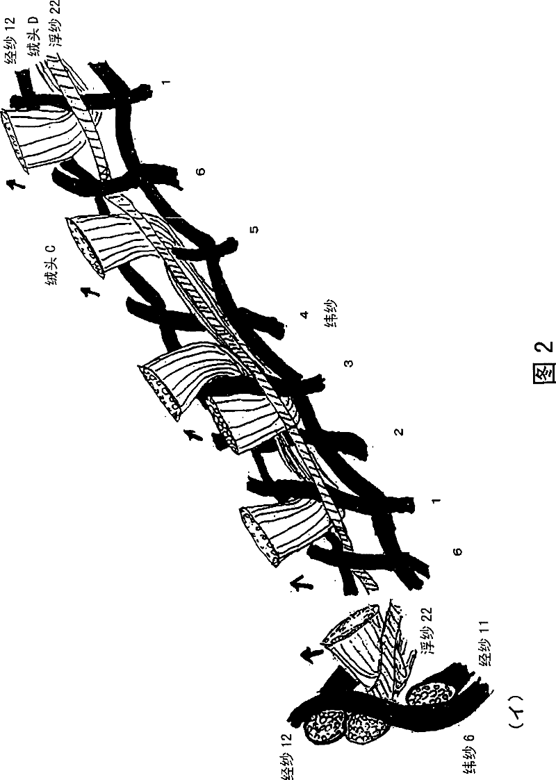
[0056] use Figure 8 The fabric structure of is woven using the same pile yarn and ground warp yarn as in Example 1. The weft yarn is 33 decitex double-ply and has a total fiber count of 74600 per square centimeter. The weaving shrinkage of floating yarn was 2.2%. The pile of the gray cloth was fixed in the same manner as in Example 1, and the angle of inclination was measured. The inclination angle of the weft direction in the above case is 74 degrees. Heat and dry the remaining gray cloth of the above-mentioned cloth at 150°C and make it shrink. After cutting, washing, and drying, use a brush to make the pile yarns tilt laterally, and coat the back of the cloth with about 50g / m 2 acrylic resin, dry and then bake. The width of the cloth after processing was 112 cm in the portion where the pile was present.


PUM

PropertyMeasurementUnit
lengthaaaaaaaaaa

Abstract

The invention provides a friction cloth for manufacturing liquid crystal panels of velvet fabric, the velvet fabric has: a base fabric structure formed by warp yarns (11)-(22) and weft yarns (1)-(6) and warp yarns along the base fabric structure Pile yarns (A) to (D) woven in the direction, the friction cloth for liquid crystal panel manufacturing is characterized in that: in a complete weave of the velvet fabric, the warp yarn has: a part (11) forming a plain weave and (12) and floating yarns (21) and (22) which are woven in a state of floating on the upper side of the weft yarn at the surface on the side where the end of the pile yarn protrudes enter.

Description

technical field [0001] The present invention relates to a rubbing cloth used in a rubbing process for controlling the orientation of liquid crystal molecules in a liquid crystal panel manufacturing process. Background technique [0002] The rubbing process refers to sticking a rubbing cloth with a fluffed pile yarn on the outer peripheral surface of a metal roller with a double-sided adhesive tape, and rotating the roller (hereinafter referred to as "rubbing roller") at a high speed to The operation of rubbing the surface of the substrate with pile yarn. Here, an alignment film formed of a dedicated polyimide resin is coated on the surface of the substrate. What the rubbing cloth rubs directly is the surface of the alignment film. The rubbing process gives the opportunity to uniformly align the liquid crystal molecular layer, that is, the polyimide molecules on the surface of the alignment film are extended in the same axial direction through the rubbing of the rubbing clo...

Claims


Application Information

Patent Timeline
Patent Type & Authority Patents(China)
IPC IPC(8): D03D1/00D03D27/00D03D27/06G02F1/1337
CPCD03D27/06G02F1/133784G02F1/1303D03D1/0088D03D13/00D10B2505/00
Inventor 广田靖保井上隆史中野敬子田平速松下道久
Owner SOMACHO
Why Eureka
Try Eureka