Carbon monoxide detecting instrument used in tunnels

A technology of carbon monoxide and detectors, applied in instruments, measuring devices, scientific instruments, etc., can solve problems affecting the accuracy of gas concentration measurement, inconvenient installation, commissioning and maintenance of detectors, and inability to predict fire disasters in time, reaching a high level Intelligence and flexibility, reduced size, small size effect

Active Publication Date: 2009-06-03
北京市华云分析仪器研究所有限公司
View PDF0 Cites 9 Cited by
  • Summary
  • Abstract
  • Description
  • Claims
  • Application Information

AI Technical Summary

Problems solved by technology

[0003] At present, the instruments for detecting the concentration of carbon monoxide in tunnels generally use open gas chambers, which can only detect the carbon monoxide gas that freely diffuses into the instrument, resulting in slow detection speed of the instrument and the inability to predict fire disasters in time
In particular, some carbon monoxide gases that are relatively far away from the detector are often not detected, which affects the accuracy of gas concentration measurement.
In addition, the traditional carbon monoxide detector includes two parts, the transmitting part and the receiving part, which are separated by several meters and arranged in parallel on one side of the tunnel, which not only occupies a large area, but also brings inconvenience to the installation, commissioning and maintenance of the detector.
The existing domestic carbon monoxide detectors for tunnels are generally imported from abroad, and the price is relatively expensive

Method used


Image

  • Carbon monoxide detecting instrument used in tunnels
  • Carbon monoxide detecting instrument used in tunnels
  • Carbon monoxide detecting instrument used in tunnels

Examples


Embodiment Construction

[0015] The present invention will be described in detail below in conjunction with the accompanying drawings and embodiments.

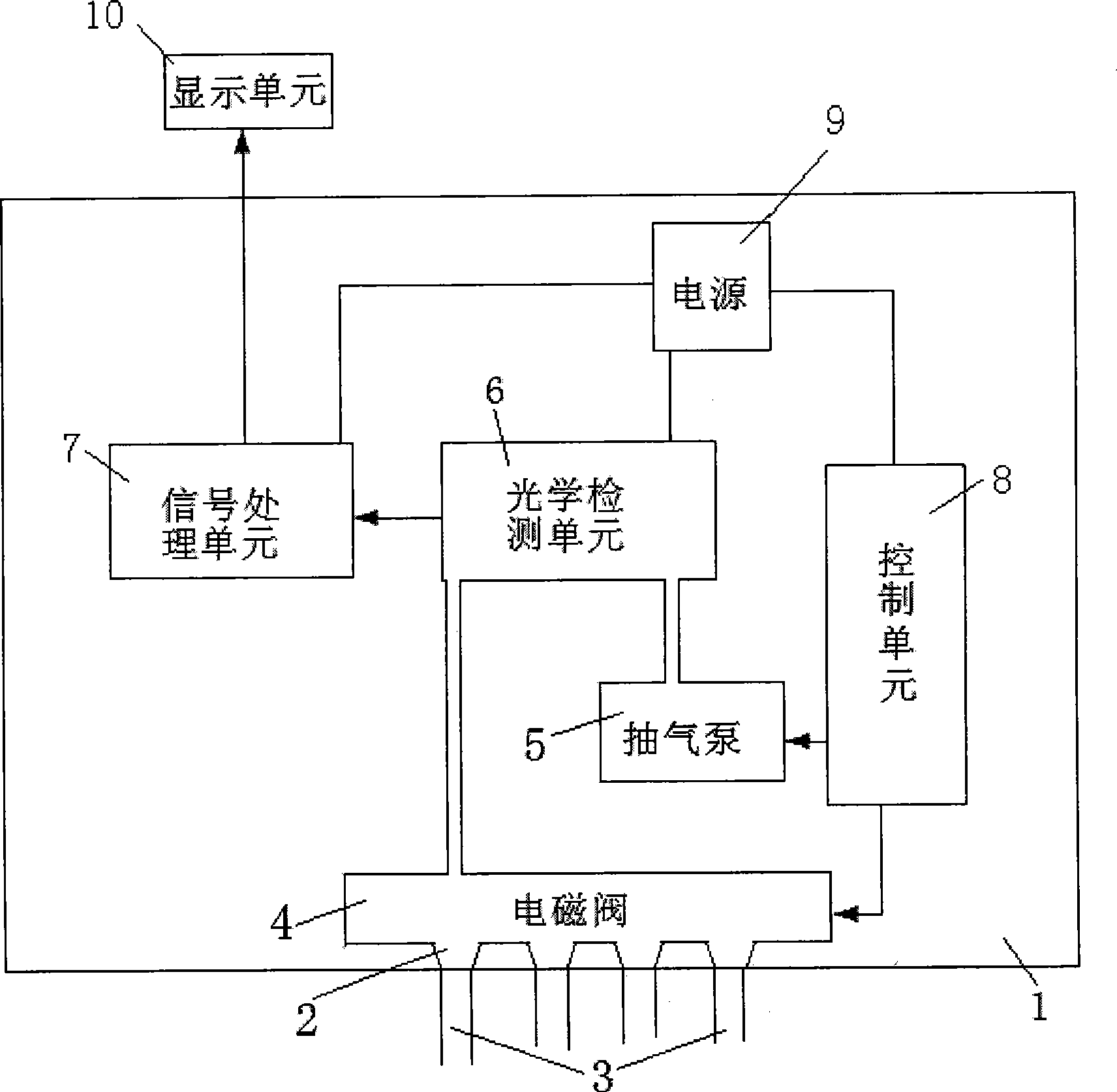
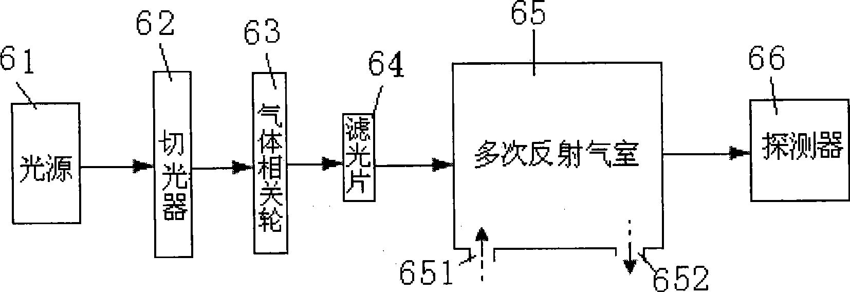
[0016] Such as figure 1 As shown, the present invention includes a closed case 1, on which four sampling gas nozzles 2 (just as an example, but not limited thereto) are arranged on the case 1 to connect with external sampling pipes 3 . Each sampling gas nozzle 2 is connected to an electromagnetic valve 4, four electromagnetic valves 4 are connected in parallel to the inlet end of an optical detection unit 6, an air pump 5 is connected to the outlet end of the optical detection unit 6, and the optical detection unit 6 is connected to the air outlet of the optical detection unit 6. A signal processing unit 7 is electrically connected. Each solenoid valve 4 and air pump 5 are electrically connected to a control unit 8 respectively, so as to realize the switch control of each solenoid valve 4 and air pump 5 by the control unit 8. The control unit 8 can u...


PUM


Abstract

The invention relates to a carbon monoxide detecting instrument used in tunnels. The detecting instrument comprises a plurality of sampling air taps arranged in an machine body and a plurality of electromagnetic valves which are correspondingly connected with the sampling air taps; each electromagnetic valve is connected in parallel at the inlet end of an optical detecting unit, and an air extracting pump is connected at the outlet end of the optical detecting unit; the optical detecting unit is electrically connected with a signal processing unit; the air extracting pump and each electromagnetic valve are electrically connected with a controlling unit; the optical detecting unit, the signal processing unit and the controlling unit are electrically connected with a power supply; the signal processing unit comprises a prime amplifier, a main amplifier, an AGC controlling unit, a peak detector, a sampling keeper, a substractor and a correcting network, a data processing unit and a communication unit, which are connected in series; a pip amplifier is connected with a logic circuit and then connected in parallel on the peak detector. The invention has the advantages that the measuring accuracy is high, the volume of the detecting instrument is small, and the detecting instrument can be widely applied to the detection of carbon monoxide gas concentration in various tunnels.

Description

technical field [0001] The invention relates to a gas detection instrument, in particular to a carbon monoxide detector for tunnels. Background technique [0002] The tunnel is a special tubular structure. There will be a lot of smoke, dust and exhaust gas emitted by vehicles in the tunnel. If these gases are not discharged in a timely and reasonable manner, the air quality and visibility in the tunnel will be directly affected, especially the exhaust emitted by vehicles. When the concentration of carbon monoxide in the exhaust gas reaches a certain proportion, it will bring serious health hazards to the driver. When a fire occurs unexpectedly in the tunnel, a large amount of carbon monoxide gas will be released. Generally, the concentration of carbon monoxide can be detected by a carbon monoxide detector, and the fire situation can be predicted at the first time, so that corresponding emergency measures can be taken to avoid the occurrence of fire. It can be seen that the ...

Claims


Application Information

Patent Timeline
Patent Type & Authority Applications(China)
IPC IPC(8): G01N21/35G01N1/24G01N21/17
Inventor 唐青云石莉雯
Owner 北京市华云分析仪器研究所有限公司
Why Eureka
Try Eureka