Plasma display device

A plasma and display device technology, applied in identification devices, housings with display/control units, gas discharge tubes/containers, etc., can solve the problems of high EMI and high manufacturing costs

Inactive Publication Date: 2009-06-03
SAMSUNG SDI CO LTD
View PDF0 Cites 21 Cited by
  • Summary
  • Abstract
  • Description
  • Claims
  • Application Information

AI Technical Summary

Problems solved by technology

The longer the FPC, the more expensive it is to manufacture and the more EMI it generates

Method used


Image

  • Plasma display device
  • Plasma display device
  • Plasma display device

Examples


Embodiment Construction

[0046] Embodiments of the present invention will be described more fully hereinafter with reference to the accompanying drawings that show exemplary embodiments of the invention. As those skilled in the art would realize, the described embodiments may be modified in various different forms, all without departing from the spirit or scope of the present invention. The drawings and descriptions are to be regarded as illustrative and not restrictive. The same reference numerals denote the same elements throughout the description.

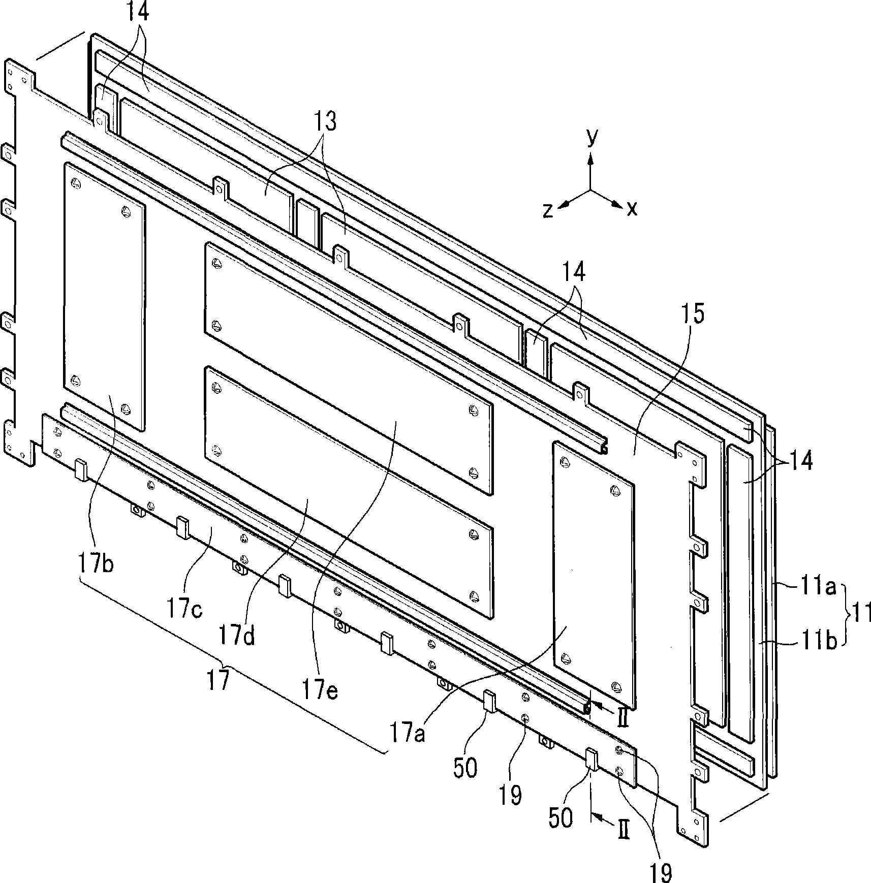
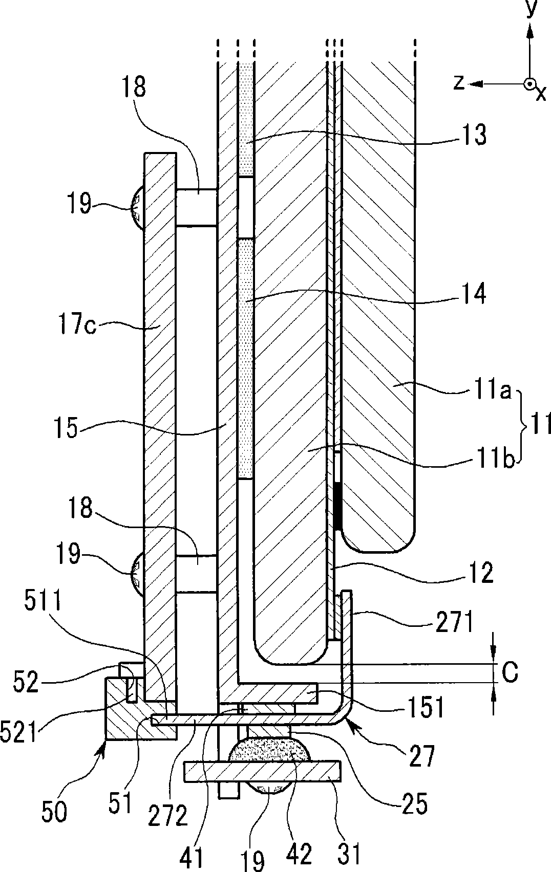
[0047] figure 1 is an exploded perspective view of a plasma display device according to an exemplary embodiment of the present invention, and figure 2 is along figure 1 A cross-sectional view of the line II-II section.

[0048] refer to figure 1 and figure 2 , the plasma display device includes a plasma display panel (PDP) 11 , a heat sink 13 , a bottom plate 15 and a printed circuit board assembly 17 .

[0049] The PDP 11 includes a front subs...


PUM


Abstract

The invention provides a plasma display device. In one embodiment, the plasma display device includes a plasma display panel, a chassis base), a printed circuit board assembly, and a flexible printed circuit. The chassis base supports the plasma display panel. The printed circuit board assembly is disposed at one side of the chassis base. The flexible printed circuit electrically connects an electrode of the plasma display panel and the printed circuit board assembly. The flexible printed circuit crosses an extension plane of the printed circuit board assembly at a predetermined angle and is connected to the printed circuit board assembly. One embodiment of the invention lowers manufacturing costs and reduces EMI by shortening a length of a flexible printed circuit.

Description

technical field [0001] The invention relates to a plasma display device. More particularly, the present invention relates to a plasma display panel that reduces manufacturing costs and electromagnetic interference (EMI) by shortening the length of a flexible printed circuit connecting a printed circuit board assembly and the plasma display panel. Background technique [0002] As is well known, a plasma display device displays images on a plasma display panel. A plasma display panel includes electrodes, such as display electrodes and address electrodes, which are electrically connected to a printed circuit board assembly through a flexible printed circuit. [0003] In more detail, the flexible printed circuit includes one end connected to electrodes, for example, by using an anisotropic conductive film (ACF), and the other end connected to a printed circuit board assembly through a connector. [0004] The plasma display panel and the chassis are arranged substantially paral...

Claims


Application Information

Patent Timeline
Patent Type & Authority Applications(China)
IPC IPC(8): G09F9/313H05K1/02H05K9/00G09F9/00
CPCH05K5/0017H05K2201/10189H05K2201/10446H05K1/147H01J11/46H01J11/34
Inventor 郑光珍
Owner SAMSUNG SDI CO LTD
Why Eureka
Try Eureka