
LED lamp

A technology of light-emitting diodes and lamps, which is applied to the semiconductor devices of light-emitting elements, lampshades, light sources, etc., and can solve problems such as limited emission angles, uneven heat dissipation, and affecting heat dissipation performance of radiators

Inactive Publication Date: 2009-06-10
FU ZHUN PRECISION IND SHENZHEN +1
View PDF0 Cites 7 Cited by
  • Summary
  • Abstract
  • Description
  • Claims
  • Application Information

AI Technical Summary

Problems solved by technology

[0004] However, because the heat dissipation fins in the middle of the radiator receive more heat from the heat source and the air convection is poorer than the heat dissipation fins near the periphery, so if the heat sources are evenly and densely arranged on a bottom plate like this, it is easy to cause uneven heat dissipation. The temperature in the middle of the bottom plate is too high relative to the surrounding area, which greatly affects the overall heat dissipation performance of the radiator.
In addition, the light source is distributed on a plane so that the outgoing angle of light is also limited to a certain extent.

Method used


Image

  • LED lamp
  • LED lamp
  • LED lamp

Examples


Embodiment Construction

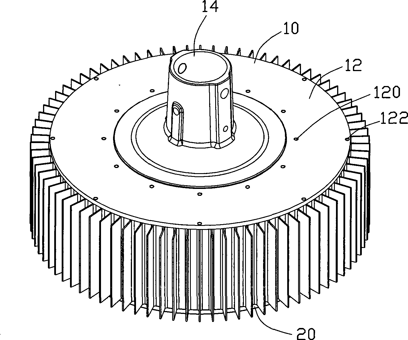
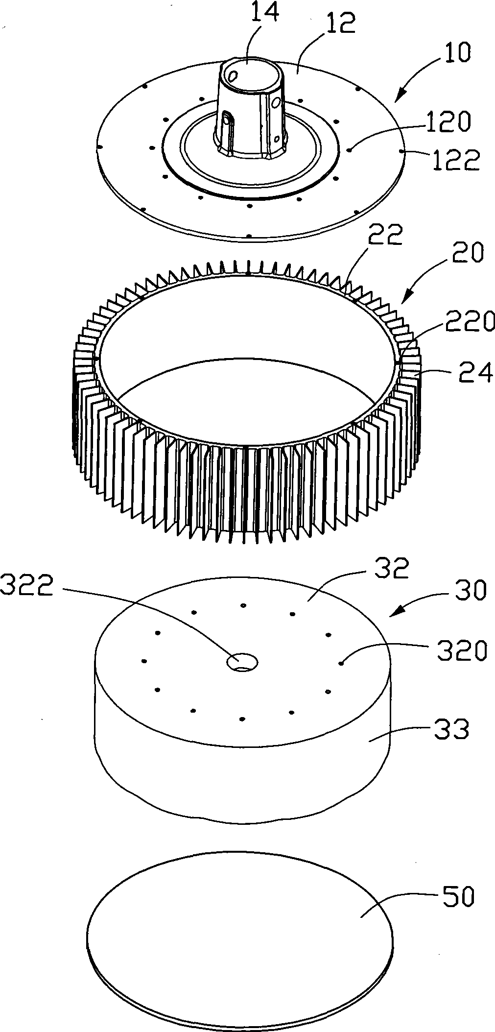
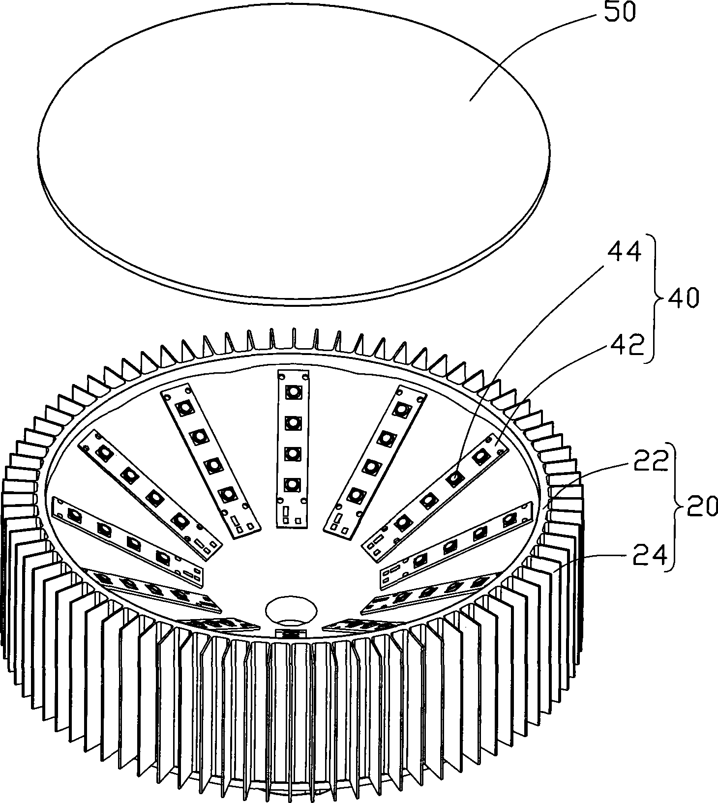
[0013] Such as Figure 1-4 As shown, the light-emitting diode lamp of a preferred embodiment of the present invention can be used for indoor or outdoor lighting in places such as squares, streets, and roads. The light-emitting diode lamp comprises a top cover 10, an annular radiator 20 connected under the periphery of the top cover 10, a heat conductor 30 accommodated in the radiator 20, and several strips attached to the bottom of the heat conductor 30. Shaped LED module 40 and a lamp cover 50 combined with the bottom edge of the heat sink 20 to seal the heat conductor 30 in the heat sink 20 .

[0014] The above-mentioned top cover 10 is used for conductively combining with a lamp holder (not shown in the figure) and at the same time fixing the entire LED lamp to the lamp holder, which includes a circular cover 12 and a lamp cap 14 arranged in the middle of the cover 12 . The cover body 12 is a circular flat body, and a plurality of spaced through holes 122 are defined near...


PUM


Abstract

The invention provides a luminescence diode lamp, which comprises a head cover, a radiator connected with the lower part of the head cover, a heat conductor and a couple of luminescence diode module groups adhibited at the lower end surface of the heat conductor; the radiator comprises a heat conducting cylinder wall and a couple of radiating rectangular fins extending outwards from the heat conducting cylinder wall; the heat radiator is contained inside the heat conducting cylinder wall and is connected with the heat conducting cylinder wall for heat conducting; the lower end surface of the heat conductor forms an inner concave used for being adhibited by the luminescence diode module groups. The air current channels between the radiating rectangular fins are arranged at the peripheral area of the heat conductor, which facilitates air taking away the heat of the radiating rectangular fins by convection from the bottom to top, thus realizing radiating effect. Meanwhile, since the luminescence diode is adhibited on the inner concave of the heat conductor, the emission angle of light is increased.

Description

technical field [0001] The invention relates to a light-emitting diode lamp, in particular to a light-emitting diode lamp with a heat dissipation structure. Background technique [0002] As an emerging third-generation light source, although it cannot replace traditional incandescent lamps on a large scale, it has the advantages of long working life, energy saving, and environmental protection, and is generally favored by the market. Moreover, the current modules composed of light-emitting diodes can produce high-power, high-brightness light sources, which can completely replace existing incandescent lamps for indoor and outdoor lighting, and will also widely and revolutionaryly replace existing light sources such as traditional incandescent lamps. And then become the main light source in line with the theme of energy saving and environmental protection. [0003] However, LEDs with higher power and brightness or their modules generate more heat, which is difficult to dissip...

Claims


Application Information

Patent Timeline
IPC IPC(8): F21V29/00H01L23/367F21V19/00F21Y101/02
CPCF21K9/00F21V29/77F21V3/061H01L2924/0002Y10S362/80H01L2924/00
Inventor 帅春江余光赖振田
Owner FU ZHUN PRECISION IND SHENZHEN
Learn More