Eureka AIR delivers breakthrough ideas for toughest innovation challenges, trusted by R&D personnel around the world.

Exhaust-heating boiler

A technology of waste heat boiler and furnace body, which is applied in the field of waste heat boiler to achieve the effect of reducing cost, reducing use and dependence, reducing investment and power consumption

Active Publication Date: 2011-01-12
CHINA ENFI ENGINEERING CORPORATION
View PDF7 Cites 0 Cited by
  • Summary
  • Abstract
  • Description
  • Claims
  • Application Information

AI Technical Summary

Problems solved by technology

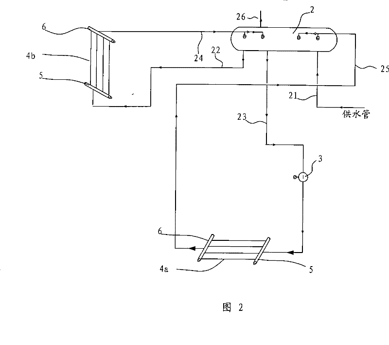
[0007] The technical problem to be solved by the present invention is to overcome the deficiencies of the above-mentioned prior art and provide a waste heat boiler with natural circulation and forced circulation. The heating surface of the waste heat boiler It is divided into natural circulation heating surface and forced circulation heating surface. The natural circulation heating surface adopts natural circulation, while the forced circulation heating surface adopts forced circulation, so as to overcome the problem that natural circulation cannot meet the forced circulation heating surface. This combination of natural circulation and forced circulation The hybrid circulation system can give full play to the advantages of the two circulations. The two circulations operate independently, which meets the requirements of the forced circulation heating surface, and the waste heat boiler does not completely rely on the forced circulation. The reliability is improved, and the investment in auxiliary equipment is low. Electric energy Less consumption, lower cost

Method used


Image

  • Exhaust-heating boiler
  • Exhaust-heating boiler
  • Exhaust-heating boiler

Examples


Embodiment Construction

[0028] Embodiments of the present invention are described in detail below, examples of which are illustrated in the accompanying drawings, wherein like reference numerals refer to like elements throughout. The embodiments described below are used to explain the present invention by referring to the figures, and the embodiments are exemplary and should not be construed as limitations of the present invention.

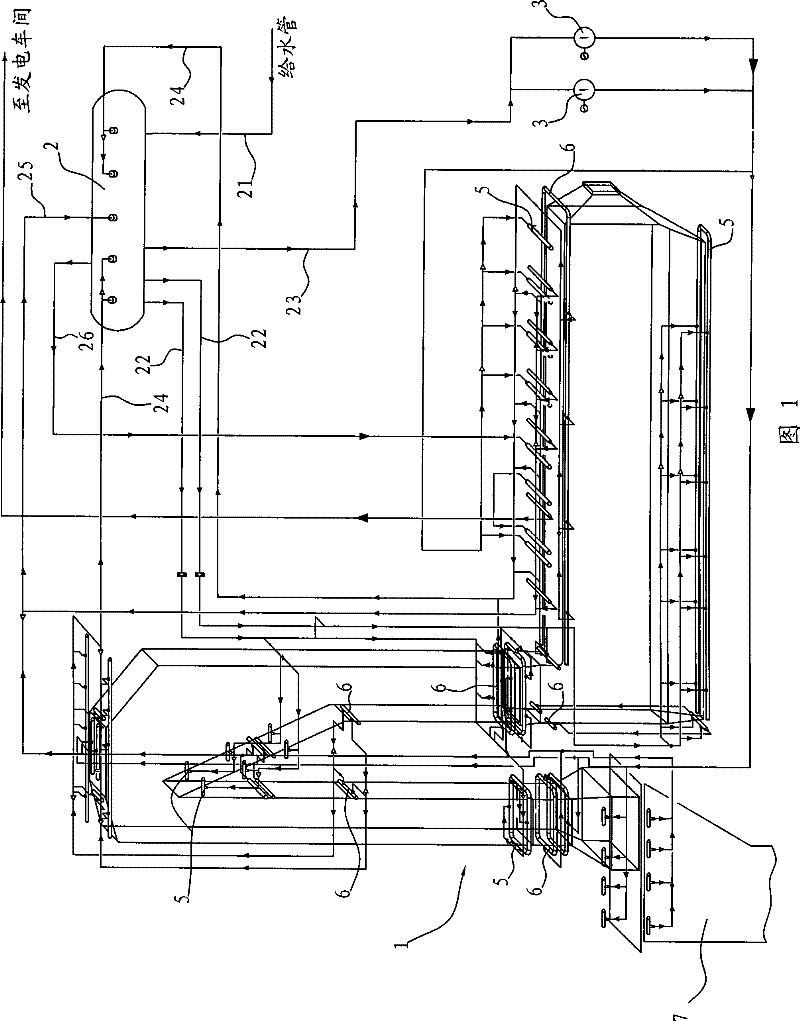
[0029] First refer to the following figure 1 A waste heat boiler according to an embodiment of the present invention is described, figure 1 is an overall schematic diagram of the waste heat boiler according to the present invention.

[0030] The waste heat boiler according to the embodiment of the present invention includes a furnace body 1 and a circulation system.

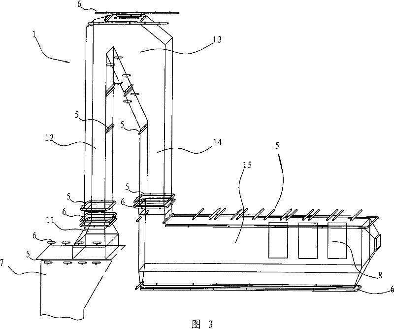
[0031] Specifically, as Figure 9 As shown, the wall of the furnace body 1 may be formed by a membrane water-cooled wall, but the present invention is not limited thereto. According to a further embod...


PUM


Abstract

The invention discloses a waste heat boiler, comprising a boiler body provided with a natural cycling heating surface and a forced cycling heating surface, a cycling system which comprises a water inlet pipe respectively arranged and used for supplying water to steam bag, a natural cycling water outlet pipe, a forced cycling water outlet pipe, a natural cycling reflux pipe, a forced cycling reflux pipe and the steam bags of a steam outlet pipe, a natural cycling heat exchanger arranged at the natural cycling heating surface the entrance and the exit of which are respectively connected with the steam bag through the natural cycling water outlet pipe and the natural cycling reflux pipe, a forced cycling heat exchanger arranged at the forced cycling heating surface the entrance and the exit of which are respectively connected with the steam bag through the forced cycling water outlet pipe and the forced cycling reflux pipe and a cycling pump arranged at the forced cycling water outlet pipe. By combining advantages of two cycling systems, the waste heat boiler overcomes limitations on the arrangement of the natural cycling heating surface and poor effects of dust removal, reduces fluxand load of the recycling pump, improves reliability, and is provided with the advantages of light accumulated dust, small volume, energy saving, etc.

Description

technical field [0001] The invention relates to a waste heat boiler, in particular to a waste heat boiler with natural circulation and forced circulation for a smelting furnace. Background technique [0002] Waste heat boilers are equipment used to recover heat. For example, in the field of nonferrous metallurgy, waste heat boilers are widely used to recover the heat in the flue gas of smelting furnaces. [0003] In the prior art, the water circulation system in the waste heat boiler adopts a single circulation mode, that is, natural circulation or forced circulation is used alone. Chinese utility model patent ZL200420008023.3 discloses a pressureless natural circulation boiler waste smoke heat recovery device, which consists of a shell, a heat absorber, a fixed plate, hot flue gas, circulating water, etc. The heat absorber is a tube type, composed of Rows of tube-type or plate-type heat sinks are connected in series, and the heat sinks are installed in the casing. It can...

Claims


Application Information

Patent Timeline
Patent Type & Authority Patents(China)
IPC IPC(8): F22B1/16F22B37/34F22D7/08
Inventor 徐建炎王岗陈逢胜张计鹏
Owner CHINA ENFI ENGINEERING CORPORATION
Why Eureka
Eureka Blog
Learn More