Al technical title is built by PatSnap Al team. It summarizes the technical point description of the patent document.
a generator and biomass technology, applied in the field of biomass generators, can solve the problems of low cost, low cost, reliable, and relatively simple need for a relatively simple, continuous-flow biomass generator that can operate, and achieve excellent aeration and temperature control, and rapid growth of a selected strain
Inactive Publication Date: 2005-02-10
NCH CORP
View PDF11 Cites 31 Cited by
Summary
Abstract
Description
Claims
Application Information
AI Technical Summary
This helps you quickly interpret patents by identifying the three key elements:
Problems solved by technology
Method used
Benefits of technology
[0012] Bacteria grown inside the biomass generator of the invention can be harvested for immediate use or stored for subsequent use as desired. The apparatus and method of the invention are especially effective for growing bacteria for a particular application at or near a preferred use site. The self-contained system of the invention can be installed inside a lockable cabinet for access only by authorized personnel. Because the cabinet can be wall mounted, no floor space is required to install the system, and the only required utilities are a water supply and a conventional 110 volt electrical outlet. Unlike systems disclosed in the prior art, the apparatus and method disclosed herein enable the user to achieve rapid growth of a selected strain of helpful bacteria by providing excellent aeration and temperature control without excessive foaming and without pump cavitation that is detrimental to long term service.
Problems solved by technology
Notwithstanding the benefits and advantages achievable through use of the previously known systems and devices, there remains a need for a relatively uncomplicated, inexpensive and reliable, continuous flow biomass generator that can operate for days or weeks without attention or operator intervention.
Method used
Image
Click on the blue label to locate the original text in one second.
Reading with bidirectional positioning of images and text.
Examples
Embodiment Construction
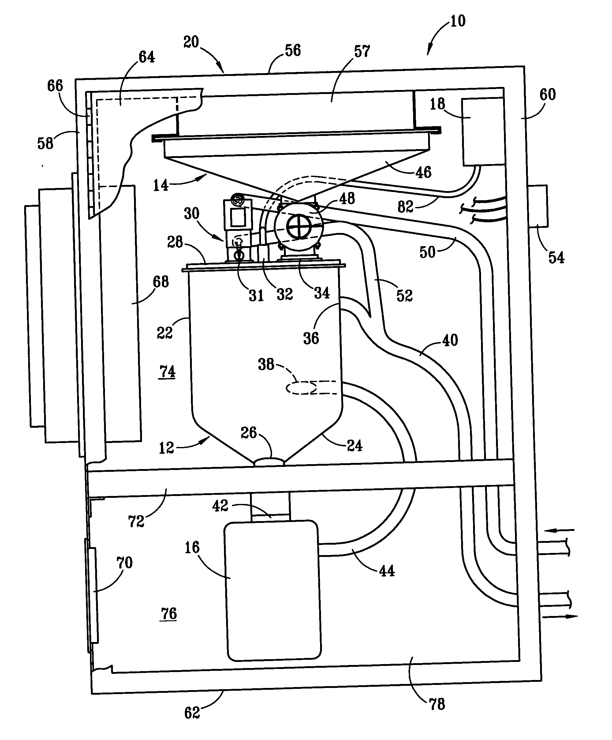
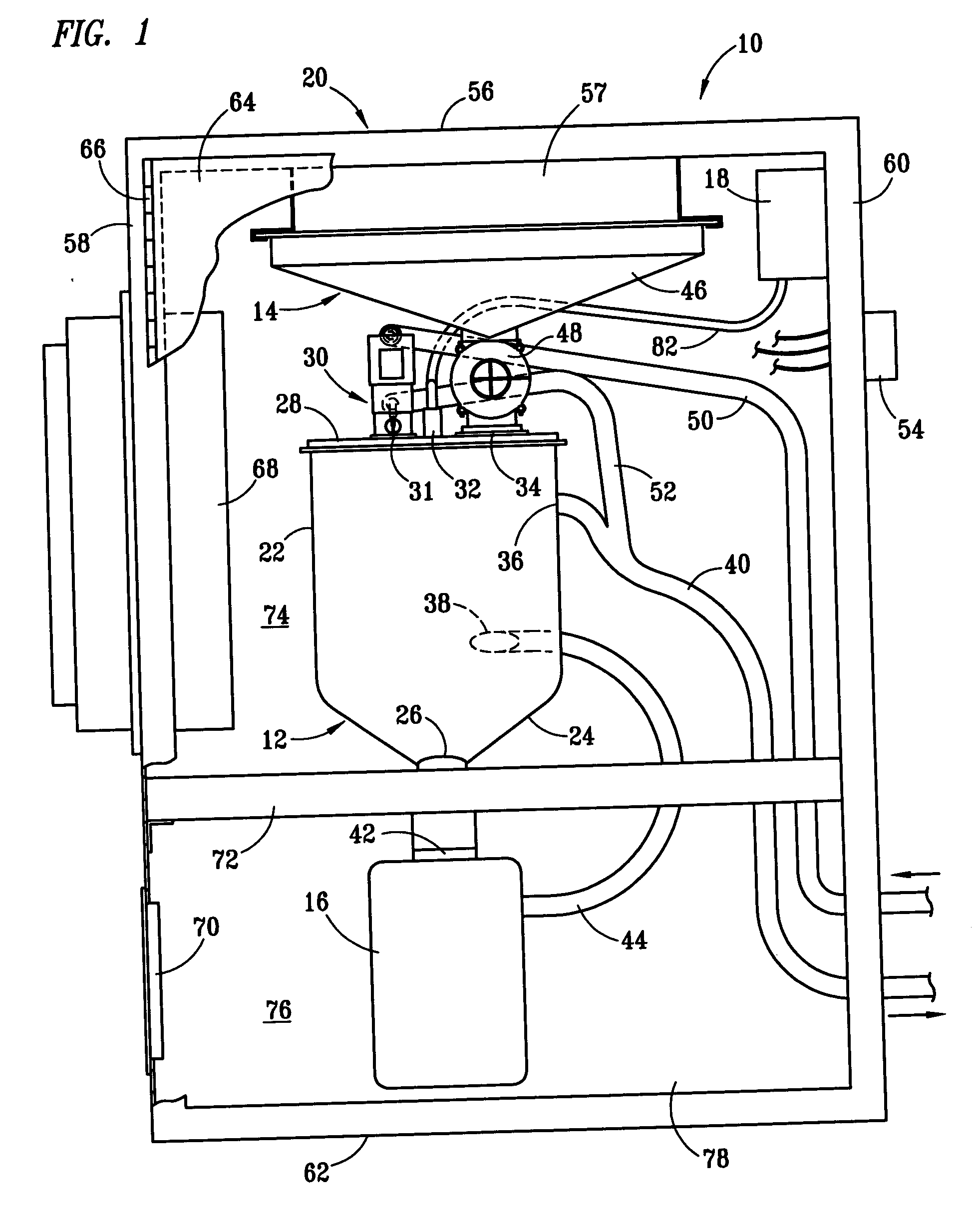
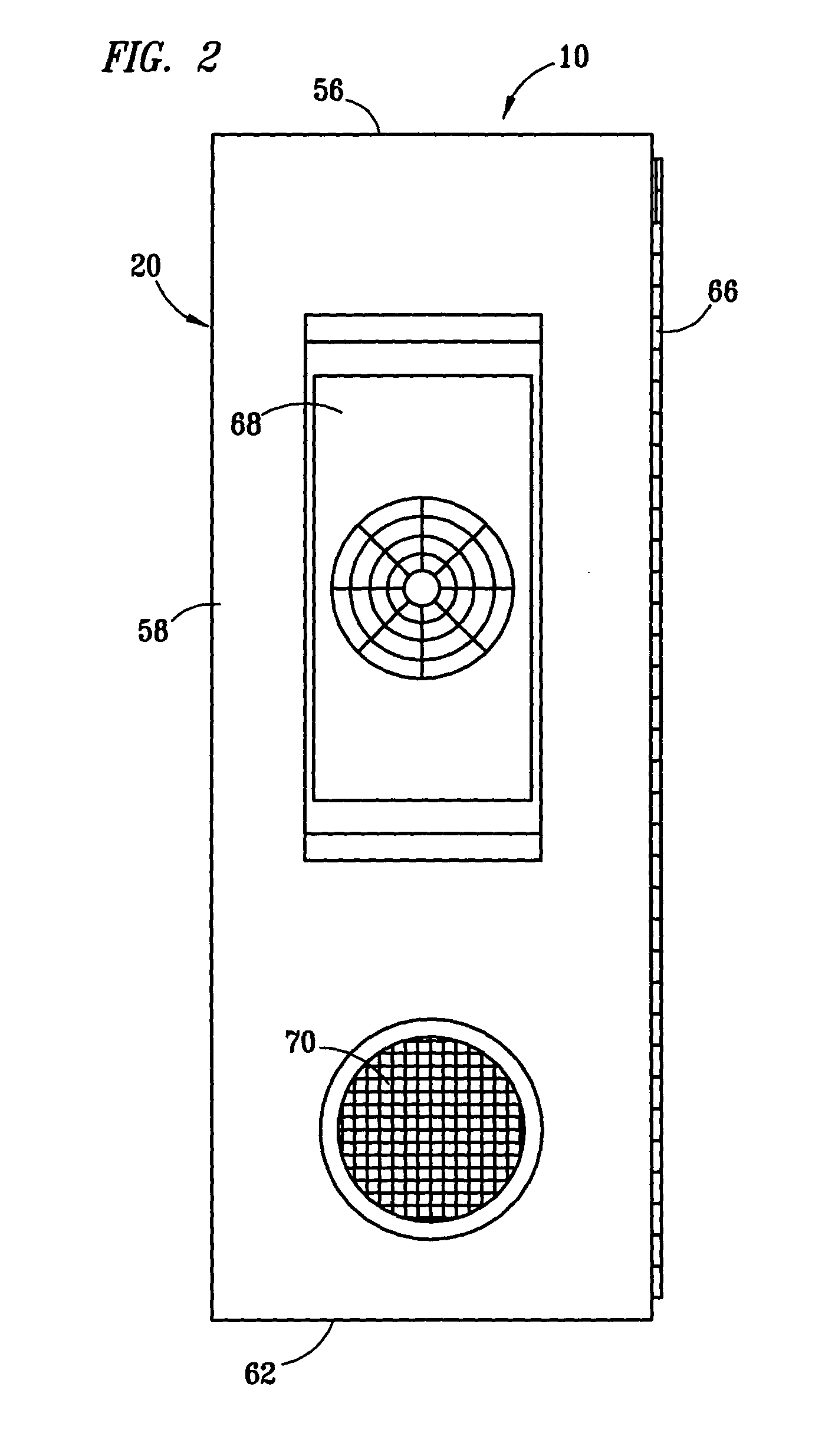
[0027] Referring to FIGS. 1-3, biomass generator 10 of the invention preferably comprises bacteria growth chamber 12, feeder mechanism 14, recirculating pump 16 and air pump 18 disposed inside cabinet 20. Cabinet 20 preferably further comprises top wall 56, back wall 57, side walls 58, 60, bottom wall 62 and door 64. Door 64 is preferably attached to cabinet 20 by hinge 66 to permit easy access to first and second interior sections 74, 76, which are separated by thermal insulation panel 72. Although not shown in the drawings, a lock or cable seal can be provided to prevent unauthorized tampering with the contents of cabinet 20 during use. According to one preferred embodiment of the invention, bacteria growth chamber 12 is made of a translucent polymeric container having an attachable cover 28. The volume of bacteria growth chamber 12 is preferably about 3 liters, although it will be appreciated that larger and smaller growth chambers can likewise be used within the scope of the inv...
PUM
Property
Measurement
Unit
temperature
aaaaa
aaaaa
temperature
aaaaa
aaaaa
volume
aaaaa
aaaaa
Abstract
A biomass generator useful for continuously growing and withdrawing bacteria to be used in a desired beneficial application, the generator having a bacteria growth chamber; water and nutrient inlet ports; upper and lower outlet ports; a recirculating pump withdrawing and reintroducing fluid to establish a vortex in the growth chamber while controlling foaming and pump cavitation; a low pressure air inlet line discharging air inside the growth chamber above the vortex; a fluid discharge line receiving bacteria-containing fluid from the upper outlet port of the growth chamber; a flush line discharging wash water into the fluid discharge line; and an electrical controller cooperating with solenoid-operated valves and a feeder mechanism to periodically introduce water and nutrients into the chamber, thereby simultaneously causing bacteria-containing fluid to be discharged from the growth chamber through the upper outlet port. A method for growing bacteria using the subject apparatus is also disclosed.
Description
BACKGROUND OF THE INVENTION [0001] 1. Field of the Invention [0002] This invention relates to apparatus and an automated method for growing and harvesting aerobic bacteria for use in various beneficial industrial, agricultural, environmental and commercial applications. [0003] 2. Description of Related Art [0004] Previously known systems for growing aerobic bacterial strains are disclosed, for example, in U.S. Pat. Nos. 4,244,815; 4,426,450; 4,888,294; 5,350,543; 5,447,866; 5,654,197; 6,168,949 B1 and 6,335,191 B1. [0005] One preferred prior art system that is useful for growing aerobic bacterial strains having desired beneficial uses is disclosed in U.S. Pat. No. 6,335,191 B1. In that system, bacteria are grown by an automated batch process and are discharged periodically, most preferably once daily, into a drain or collection vessel. Other prior art systems and apparatus for growing bacteria are disclosed, for example, in the prior art cited in U.S. Pat. No. 6,335,191 B1. [0006] N...
Claims
Application Information
Patent Timeline
Application Date:The date an application was filed.
Publication Date:The date a patent or application was officially published.
First Publication Date:The earliest publication date of a patent with the same application number.
Issue Date:Publication date of the patent grant document.
PCT Entry Date:The Entry date of PCT National Phase.
Estimated Expiry Date:The statutory expiry date of a patent right according to the Patent Law, and it is the longest term of protection that the patent right can achieve without the termination of the patent right due to other reasons(Term extension factor has been taken into account ).
Invalid Date:Actual expiry date is based on effective date or publication date of legal transaction data of invalid patent.
Patent Type & Authority Applications(United States)