Non- reference lamb wave damnification monitoring method based on double-element piezoelectric sensor array and time window function

A sensor array, dual-element piezoelectric technology, applied in the direction of using sonic/ultrasonic/infrasonic waves to analyze solids, etc., can solve the problems of inability to monitor, difficult, and weak damage to scattered signal energy.

Active Publication Date: 2009-06-10
NANJING UNIV OF AERONAUTICS & ASTRONAUTICS
View PDF0 Cites 37 Cited by
  • Summary
  • Abstract
  • Description
  • Claims
  • Application Information

AI Technical Summary

Problems solved by technology

However, since this method requires the healthy signal as a reference, there are big problems in the application under real conditions: because the reference signal and the current structure response signal have different acquisition times, there is a certain time interval, and it is difficult to ensure the structure and external conditions under real conditions. The conditions do not change, but slight changes will cause changes in the structural response signal, such as ambient temperature, structural boundaries and stress conditions, external vibration, etc., and the performance of the driver / sensor is also affected by factors such as temperature, due to damage to the scattering signal The energy itself is weak. When the method based on the reference signal is used, the damage scattering signal is easily submerged in the signal changes and noise caused by the structure and external condition changes, and it is difficult to realize damage monitoring; at the same time, when the reference signal is collected When there is already damage in the previous structure, the method based on the reference signal cannot extract the damage scattering signal generated by the damage, so it cannot monitor it

Method used


Image

  • Non- reference lamb wave damnification monitoring method based on double-element piezoelectric sensor array and time window function
  • Non- reference lamb wave damnification monitoring method based on double-element piezoelectric sensor array and time window function
  • Non- reference lamb wave damnification monitoring method based on double-element piezoelectric sensor array and time window function

Examples


Embodiment Construction

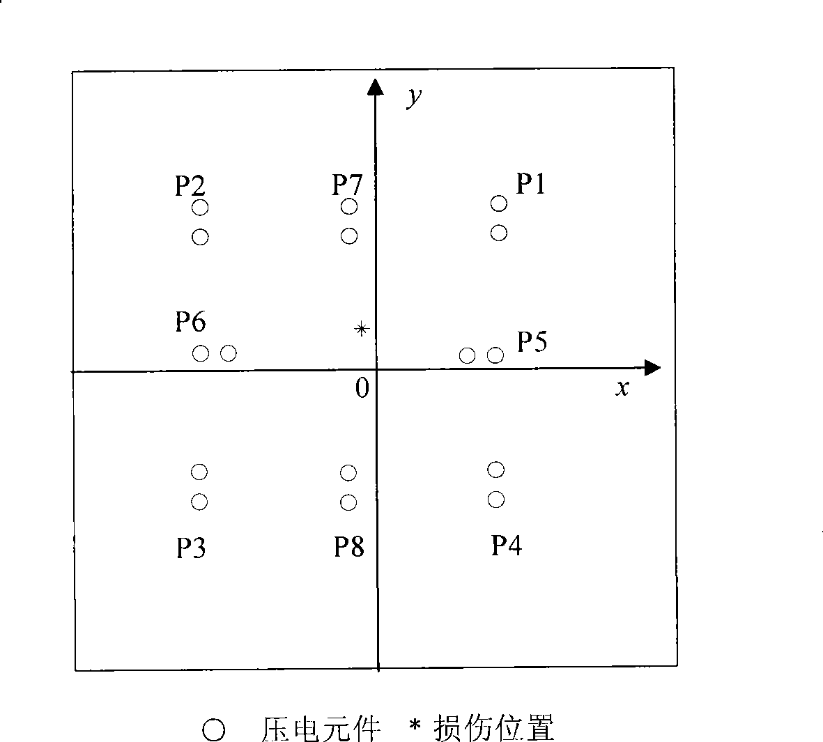
[0030] Such as image 3 As shown, the structure to be monitored is an epoxy glass fiber composite board with a size of 1126mm×990mm×2mm. The damage is simulated by loading the mass block. The coordinate position of the damage is (-13mm, 35mm), and the diameter is about 19mm .

[0031] This embodiment includes the following steps:

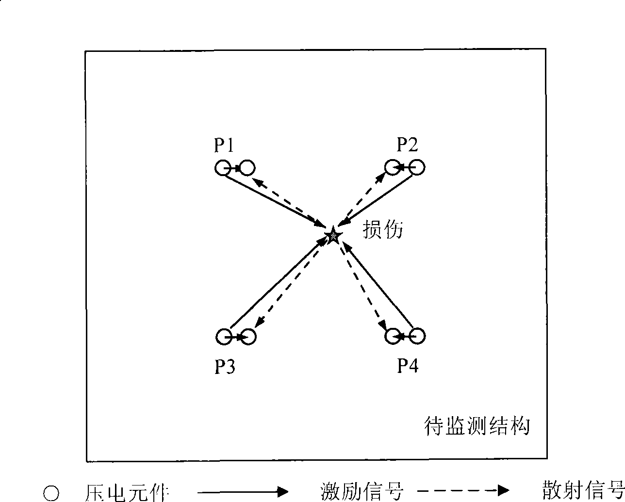
[0032] Step 1: Arrange the dual-element piezoelectric sensor array, and use the structure according to the monitoring range and area figure 1 8 pairs of piezoelectric elements are arranged in the form of a sensing / excitation array, and the schematic diagram of the piezoelectric array position is shown in image 3 As shown, the coordinates of the actuator and the sensor are shown in Table 1, the origin of the coordinates is the center point of the plate, the center distance between each pair of piezoelectric sheets is 3cm, and the diameter is 0.8cm;

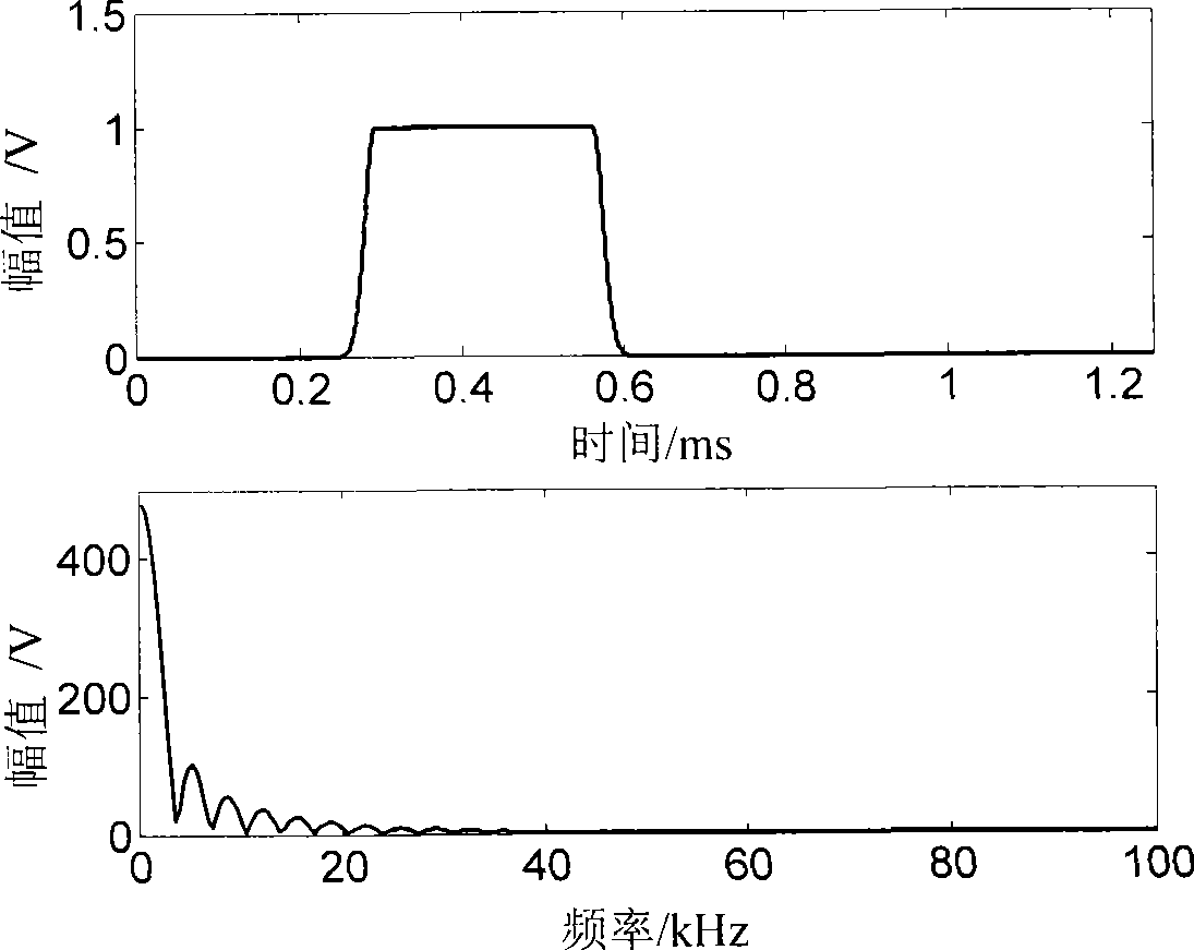
[0033] Step 2: Load the set narrowband signal to the piezoelectric element as the driver in a selec...


PUM


Abstract

The invention discloses a non-reference Lamb wave damage monitoring method based on a unit doublet piezoelectricity sensor array and time window functions, comprising the steps: arranging the unit doublet piezoelectricity sensor array in the structure; loading Lamb wave narrow band signals onto a piezoelectricity unit; performing further normalization process on the collected structural response signals; separating and obtaining structural impair scattered signals; obtaining structural scatteringin signals; judging structural impair condition. The method realizes separation of the scatteringin signals with direct sense signals, border reflection signals under the drive of initiative Lamb wave; having no use for the structural response signals under healthy condition as the reference signals, monitoring the structure at any time; without changing or increasing the device and the parameter, realizing only through a general hardware system; realizing monitoring without processing or computing impair characteristic parameters at the arrival of the impair scattered signal in the signals.

Description

1. Technical field [0001] The invention relates to a damage monitoring method of an engineering structure, in particular to a damage monitoring method of an engineering structure which does not need a priori test signal as a damage monitoring reference, which is realized by a dual-element piezoelectric sensing array. 2. Background technology [0002] With the continuous improvement of structural safety and reliability requirements, the on-line monitoring and diagnosis of structural damage has attracted more and more attention. In order to prevent disasters or losses caused by structural damage, effective monitoring of structures is necessary. Plate or shell structures are one of the main forms of engineering structures, and the research on online damage monitoring of such structures is a hotspot in the research of structural health monitoring technology. Active Lamb wave technology is a kind of damage monitoring technology for plate or shell structures that has been studied ...

Claims


Application Information

Patent Timeline
Patent Type & Authority Applications(China)
IPC IPC(8): G01N29/04
Inventor 王强袁慎芳邱雷蔡建苏永振张逍越
Owner NANJING UNIV OF AERONAUTICS & ASTRONAUTICS
Why Eureka
Try Eureka