
Field emission type electronic source and manufacturing method thereof

An electron source, field emission technology, applied in cathode ray tube/electron beam tube, electrode system manufacturing, discharge tube/lamp manufacturing, etc. It is difficult to solve problems such as electron source, so as to achieve the effect of increasing the voltage and increasing the insulation distance

Active Publication Date: 2009-06-10
TSINGHUA UNIV +1
View PDF0 Cites 9 Cited by
  • Summary
  • Abstract
  • Description
  • Claims
  • Application Information

AI Technical Summary

Problems solved by technology

The disadvantage of this structure is that the emitter density is too high, the electric field shielding effect is serious, and only a small part of the emitter emits electrons when working, so it is difficult to make an electron source with high current density.
In addition, the insulation design of the isolator of the field emission electron source is not optimal, which limits the working voltage applied between the metal grid and the cathode electrode.

Method used


Image

  • Field emission type electronic source and manufacturing method thereof
  • Field emission type electronic source and manufacturing method thereof
  • Field emission type electronic source and manufacturing method thereof

Examples


Embodiment Construction

[0015] The technical solution will be further described in detail below in conjunction with the accompanying drawings.

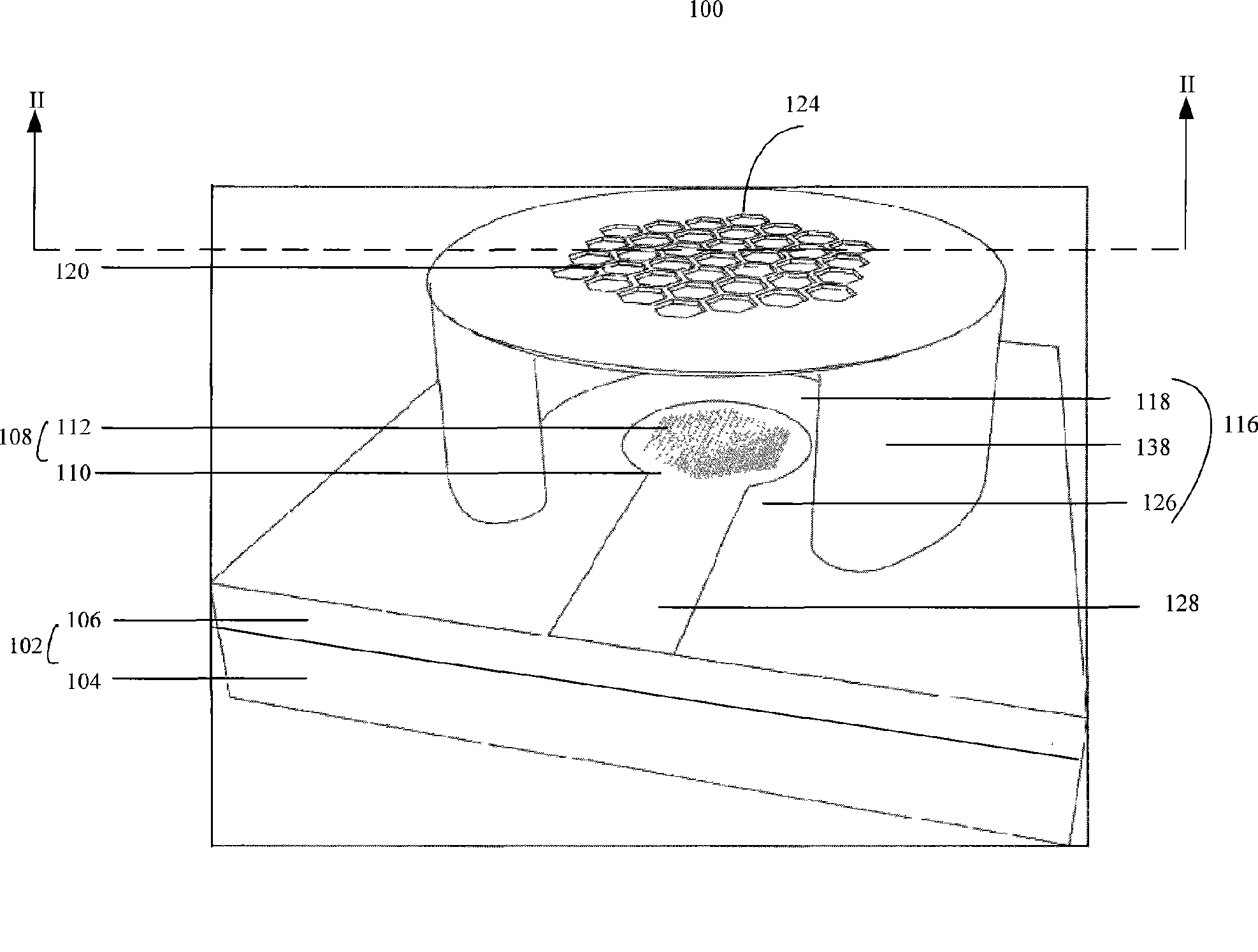
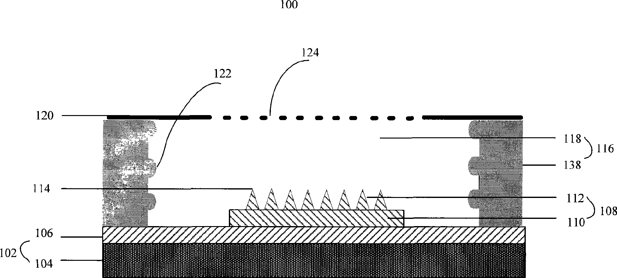
[0016] see figure 1 and figure 2 The embodiment of the technical solution provides a field emission electron source 100, which includes: an insulating substrate 102, a cathode emitter electrode 108 disposed on the upper surface of the insulating substrate 102, and a spacer 116 disposed on the upper surface of the insulating substrate 102, And a metal grid 120 is disposed on the separator 116, and the metal grid 120 further extends above the cathode emitter electrode 108, wherein the cathode emitter electrode 108 includes a cathode electrode 110 and a cathode emitter 112 disposed on the on the cathode electrode 110.

[0017] The insulating substrate 102 is an insulating substrate, such as an SOI (Silicon-On-Insulator, silicon on insulating substrate) substrate or a glass substrate. In this embodiment, an SOI substrate is preferably used as the insulating ...


PUM


Abstract

The invention discloses a field emission electron source, which comprises an insulation substrate. A cathode emission electrode is arranged on the insulation substrate and comprises a cathode electrode and a cathode emitter arranged on the cathode electrode; an isolated body is arranged on the insulation substrate; and a metal grid mesh is arranged on the isolated body and further extends above the cathode emission electrode, wherein the isolated body and the cathode electrode are arranged at intervals. A method for preparing the field emission electron source comprises the following steps: providing an insulation substrate; preparing a cathode emission electrode on the insulation substrate, wherein the cathode emission electrode comprises a cathode electrode and a cathode emitter arranged on the cathode electrode; preparing a prefabricated body of the isolated body on the insulation substrate and exposing the prefabricated body of the isolated body; manufacturing a metal grid mesh on the prefabricated body of the isolated body; removing the exposed part of the prefabricated body of the isolated body and arranging the isolated body and the cathode electrode at intervals; therefore, the field emission electron source is obtained.

Description

technical field [0001] The invention relates to an electron source and a preparation method thereof, in particular to a field emission electron source and a preparation method thereof. Background technique [0002] The field emission electron source is an electron source that uses electrons escaping from the surface of solid materials to achieve electron emission under the action of an external field. The field emission electron source works at low temperature or room temperature. Compared with the thermal emission electron source in the electric vacuum device, it has the advantages of low energy consumption, fast response speed and low discharge. Therefore, the field emission electron source is used to replace the thermal emission in the electric vacuum device. Electron sources have become a hotspot of research. [0003] Early field emission electron sources used Spindt microtip structures as field emission arrays. This electron source manufactured based on micro-nano pro...

Claims


Application Information

Patent Timeline
Patent Type & Authority Applications(China)
IPC IPC(8): H01J1/304H01J9/02
CPCH01J2201/30496H01J31/127H01J2201/30484H01J2201/30492H01J2203/0272H01J1/304H01J3/021H01J9/025
Inventor 潜力刘亮范守善
Owner TSINGHUA UNIV
Learn More