Incoherent retrospective dynamic transmit focusing

A technology for transmitting beams and echo signals, which is applied in the field of medical diagnostic ultrasound systems and can solve problems such as limited energy and reduced image contrast.

Active Publication Date: 2009-06-10
KONINKLIJKE PHILIPS ELECTRONICS NV
View PDF4 Cites 25 Cited by
  • Summary
  • Abstract
  • Description
  • Claims
  • Application Information

AI Technical Summary

Problems solved by technology

A disadvantage is that r.f. signals from the entire image field must be stored for processing
This requires a considerable amount of information storage
The second disadvantage is that a considerable amount of processing is required to select and weight the data for each point in the image, and then combine the appropriately weighted data to compute the image data points
A third disadvantage is that this scheme is only effective for very shallow penetration depth

Method used


Image

  • Incoherent retrospective dynamic transmit focusing
  • Incoherent retrospective dynamic transmit focusing
  • Incoherent retrospective dynamic transmit focusing

Examples


Embodiment Construction

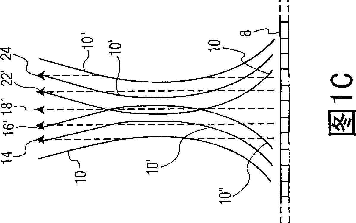
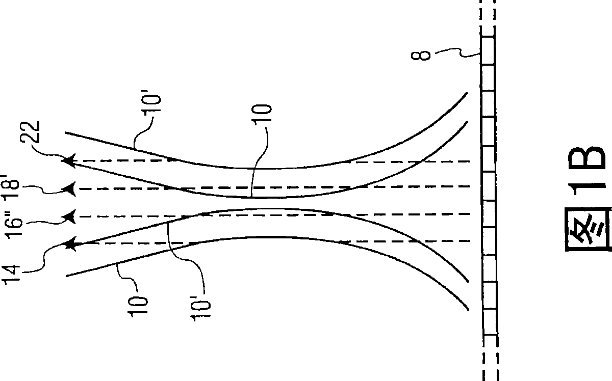
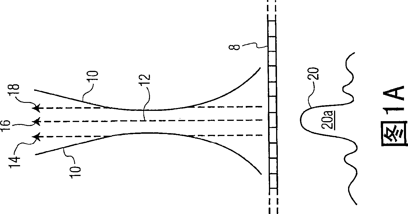
[0015] Referring first to Figures 1a-1c, overlapping beam profiles are shown for the transmission of three transmit beams, followed by the reception of three beams from each transmit beam in each case. Figure 1a shows a transmit beam profile 10 emitted by and extending from a transducer array 8 of the transmit beam, having a constant level below the intensity peak at the center of the beam. The transmit beam profile level is chosen by the designer, which may be 3dB, 6dB, 20dB or some other level below the maximum intensity at the center of the beam. It can be seen that the beam profile is focused by conventional transmit focusing around the focal point 12 at the narrowest width of the beam profile. Below the transducer array 8 is shown an orthogonal view of the beam 20, which can be seen to comprise a central lobe 20a and side lobes on either side of the main lobe 20a. The transmitted beam reaches its tightest focus at the focal zone 12 and diverges thereafter. In other impl...


PUM


Abstract

An ultrasonic diagnostic imaging system produces an image with an extended focal range by transmitting a plurality of beams spaced along an array for multiline reception. The receive multilines of a plurality of transmit beams are spatially aligned and are combined with phase adjustment between the respective receive multilines to prevent undesired phase cancellation. The combined multilines produce the effect of an extended transmit focus so that an image produced using the combined multilines exhibits an extended focal range. To prevent motion artifacts the multiline order is adjustable as a function of image motion.

Description

technical field [0001] The present invention relates to medical diagnostic ultrasound systems, and more particularly, to ultrasound systems that use multiline receive beamformers to expand the focal zone. Background technique [0002] The principle of synthetic focusing, by means of which the ultrasound image is focused at each point in the image field, is the subject of investigation. For example, US Patent 4,604,697 (Luthra et al.) describes a synthetic focusing technique in which ultrasound pulses are emitted sequentially from each element of an ultrasound transducer array. Echo signals received from each transmission are received by all elements of the array and stored. After all signals have been received, focused echoes can be formed at each point in the image field based on knowledge of the position of each transducer element relative to each point in the image and the transit time of the ultrasound signal to and from each point Signal. The appropriate received sig...

Claims


Application Information

Patent Timeline
IPC IPC(8): A61B8/00
CPCG01S7/5209G01S7/52095G01S7/52047G01S7/52028
Inventor J·罗贝尔M·伯切
Owner KONINKLIJKE PHILIPS ELECTRONICS NV
Why Eureka
Try Eureka