Electric device probe expansion device and expansion-probe control method of main frame

A technology for expansion devices and electronic equipment, which is applied in electrical digital data processing, medical science, instruments, etc., can solve the problems of expensive high-voltage switches, unfavorable console placement, and electric shocks for operators, achieving compact structure and eliminating high-voltage electric shocks risk, the effect of a high degree of operation automation

Active Publication Date: 2009-06-17
SHENZHEN MINDRAY BIO MEDICAL ELECTRONICS CO LTD +1
View PDF0 Cites 13 Cited by
  • Summary
  • Abstract
  • Description
  • Claims
  • Application Information

AI Technical Summary

Problems solved by technology

The external connection of high-voltage power supply is likely to cause the danger of electric shock for operators; and the high-voltage switch is expensive, which makes the cost of the whole module more expensive
[0009] In addition, the existing probe expansion device is bulky, which is not conducive to placing it on the operating table

Method used


Image

  • Electric device probe expansion device and expansion-probe control method of main frame
  • Electric device probe expansion device and expansion-probe control method of main frame
  • Electric device probe expansion device and expansion-probe control method of main frame

Examples


Embodiment 1

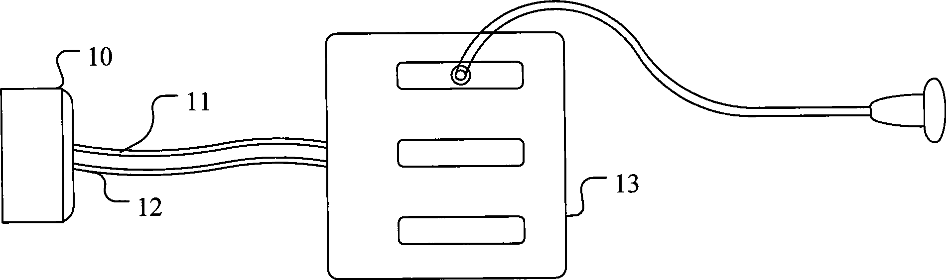
[0041] Please refer to figure 2 Schematic diagram of the structure. The probe expansion device of this example is applied to an ultrasonic diagnostic system, and its hardware structure mainly includes several parts such as a plug 10, a power supply and a control cable 11, a transmitting / receiving signal cable 12, and a main body 13. The plug 10 of the probe expansion device is the same as that of a general The interface of the probe plug has the same definition, and it is connected to the probe socket of the host of the ultrasonic diagnostic equipment when in use.

[0042] The power supply and the control signal share one cable, and the transmission / reception signal of the system uses a separate cable. The cables are all shielded multi-core cables to ensure that the device has good anti-interference ability and reduces its own mutual interference.

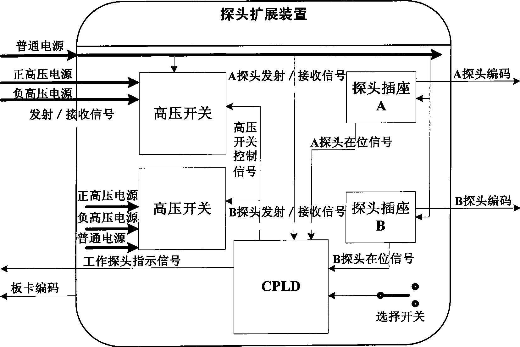
[0043] The main body of the probe expansion device implements the main functions of the device, and all related operations are ...

Embodiment 2

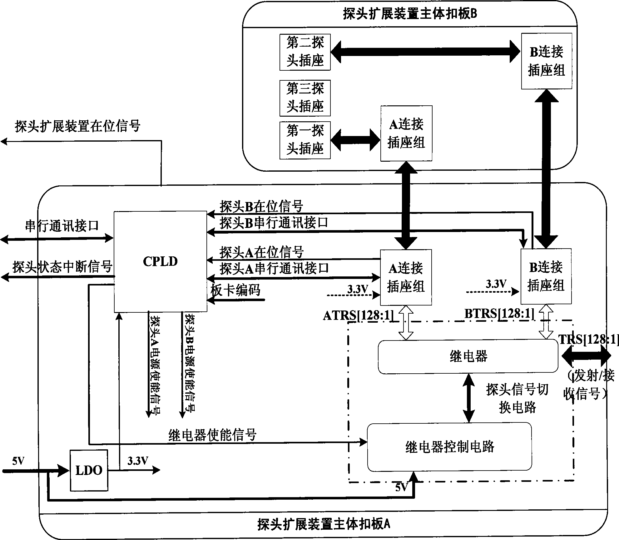
[0069] In this example, the principles of layout and control methods are the same as those of the previous example; Figure 10 As shown, this example adds a second-level signal switching circuit, which can realize the expansion of 4 probe sockets.


PUM


Abstract

The present invention discloses a probe expanding device of electronic equipment and a method for controlling expanding probe by the host machine, wherein the device comprises a body and a probe expanding device plug. The body is provided with a controller, a probe signal commutation circuit, a first probe socket, a second probe socket and a probe expanding device plug. A host machine determines whether the reading of expanding probe is finished and enquires the on-position state of probe through a controller of probe expanding device. The probe which is to be executed with information reading transmits a power supply enable signal through a controller for supplying power to the corresponding probe. The communication interface of corresponding probe is gated for reading probe information. When the host machine confirms that the probe information reading is finished, a probe de-electrifying command is transmitted to the controller by the host machine. The controller controls the power supply enable signal. The corresponding probe is de-electrified and the operation is finished. An interface communication connection is realized between the probe expanding device and the host machine device according to the invention. An inner controller analyzes command of host machine system and realizes the functions of probe identifying, working probe switching, etc. The control to various functions is conveniently and reliably executed. The automatization degree of operation is high.

Description

【Technical field】 [0001] The invention relates to a circuit device and a control method, in particular to a structure of a probe expansion device used in electronic equipment and a related control method. 【Background technique】 [0002] In the prior art, some electronic devices, such as portable ultrasonic diagnostic equipment, have only one socket for an ultrasonic probe on the host device due to their own portability requirements and structural characteristics. Such a structure increases the frequency of replacement of the ultrasound probe by the doctor during the use of the ultrasound equipment, and increases the possibility of damage to the plug of the ultrasound probe during operation. Therefore, a probe expansion device for portable ultrasonic diagnostic equipment has appeared, which is used to increase the probe interface of the system. This expansion device can reduce the replacement of the probe to a certain extent and avoid damage. [0003] The operation of the ul...

Claims


Application Information

Patent Timeline
Patent Type & Authority Applications(China)
IPC IPC(8): A61B8/00G06F13/38
Inventor 宋炜华刘国涛程东彪
Owner SHENZHEN MINDRAY BIO MEDICAL ELECTRONICS CO LTD
Why Eureka
Try Eureka