Automatic feeding device for mixed flow assembly line

A technology of automatic feeding and assembly line, used in transportation and packaging, metal processing equipment, metal processing and other directions, can solve the problems of poor versatility, large size, and inability to distinguish different parts.

Inactive Publication Date: 2009-06-17
HUAZHONG UNIV OF SCI & TECH
View PDF2 Cites 11 Cited by
  • Summary
  • Abstract
  • Description
  • Claims
  • Application Information

AI Technical Summary

Problems solved by technology

Although this equipment can be applied to the assembly line of large parts, it is bulky and cannot distinguish different parts. It can only be used in conjunction with a special assembly line, and its versatility is not strong.

Method used


Image

  • Automatic feeding device for mixed flow assembly line
  • Automatic feeding device for mixed flow assembly line
  • Automatic feeding device for mixed flow assembly line

Examples


Embodiment Construction

[0016] The present invention will be described in further detail below in conjunction with accompanying drawing and example.

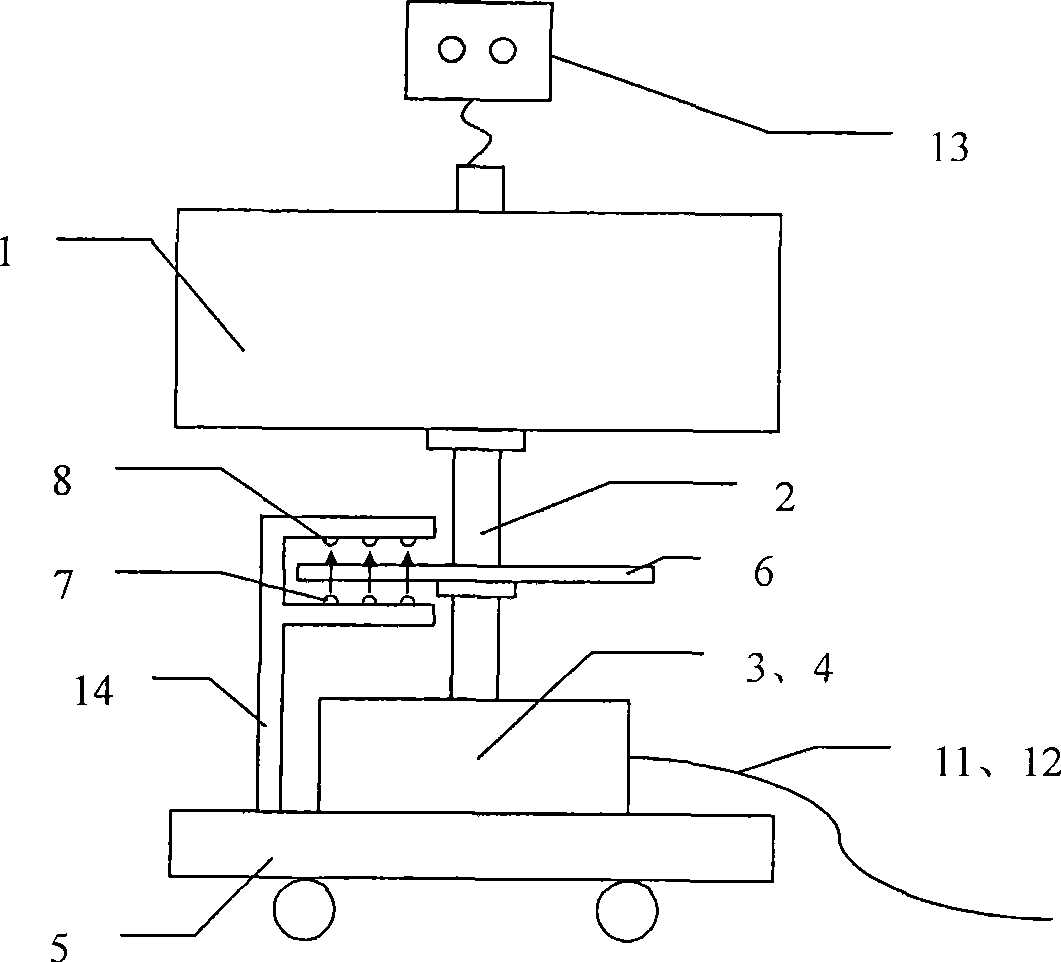
[0017] like figure 1 Shown, base 5 has rollers, so that the worker moves device. A photodetector 14 , a controller 3 and a motor 4 are fixed on the base 5 . The photodetector 14 is located next to the grating 6 and consists of a light emitting diode 7 and a photodiode 8 . The controller 3 is connected to the motor 4, analyzes and judges the WIP information of the mixed flow assembly line transmitted from the bus 12, calculates the rotation angle of the motor 4, and sends a pulse signal to drive the motor 4. The controller 3 is pre-configured with station part information, including the name, size, quantity of all parts to be assembled, the number of the trough where they are located, and the assembly sequence composed of all parts to be assembled. The motor 4 is connected to the bottom of the shaft 2 and can rotate at the same speed as the shaft 2. ...


PUM


Abstract

The invention relates to an automatic feeding device for a mixed flow assembly line, which comprises a shaft, a turntable, an optical grating, an optoelectronic detector, a controller and a motor. The bottom end of the shaft is connected with the motor, the middle part of the shaft is fixed with the optical grating and the turntable from the bottom to top, the motor is connected with the controller, and the controller is also connected with the optoelectronic detector which is close to the optical grating. The turntable is provided with at least two sector troughs which are corresponding to the amount and the position of the sectors of the optical grating, and the serial numbers of the troughs are corresponding to the photoelectric codes of the sectors of the optical grating. The automatic feeding device automatically delivers right materials to workers at hand by accurately identifying and positioning the troughs so as to reduce the error rate of mixed flow assembly.

Description

technical field [0001] The invention relates to the technical field of material supply, in particular to an automatic feeding device for a mixed flow assembly line. Background technique [0002] The mixed-flow assembly line is used for mixed-flow assembly of multiple products of the same type. The common parts on the assembly station are often small in size and large in number, and there are a large number of different parts (ie parts with similar shapes and sizes). These different parts are similar in appearance and are not easy to distinguish manually. If workers are not familiar with the assembly process of various products during product switching, or misidentify different parts, it is very easy to install the wrong parts. [0003] The invention patent document of application number 200510021316.X "Apparatus and method for packaging and providing small parts" provides a distribution technology for providing small parts to assembly line operators conveniently and smoothl...

Claims


Application Information

Patent Timeline
Patent Type & Authority Applications(China)
IPC IPC(8): B23P19/00B65G29/00
Inventor 饶运清王昆鹏王孟昌刘伦洪邵新宇张国军刘琼张超勇
Owner HUAZHONG UNIV OF SCI & TECH
Why Eureka
Try Eureka