Differential pressure sensor

A differential pressure sensor and sensing element technology, applied in instruments, measuring fluid pressure, measuring pressure difference between multiple valves, etc., can solve the problems of low static pressure, high cost, and inability to output electrical signals, etc. Achieve the effect of increased static pressure and simple preparation process

Active Publication Date: 2009-06-17
ZHONGSHAN TIANYUAN VACUUM EQUIP TECH CO LTD
View PDF0 Cites 6 Cited by
  • Summary
  • Abstract
  • Description
  • Claims
  • Application Information

AI Technical Summary

Problems solved by technology

For Bourdon tube type and bellows type differential pressure sensors, the positive and negative pressure chambers are the same elastic element, and the pressure acts on one side of the elastic element, so there is a problem of low static pressure in use
The structure of the diaphragm type differential pressure sensor is complex, and the interior needs to be filled with oil and vacuumized, which makes the cost higher
At the same time, these differential pressure sensors only have a mechanical gauge display, cannot output electrical signals, and cannot be connected to an automatic control system. Therefore, they cannot effectively control the rate of change of internal and external pressure of containers and equipment and the size of the pressure difference, which greatly restricts the differential pressure. Sensor application

Method used


Image

  • Differential pressure sensor
  • Differential pressure sensor
  • Differential pressure sensor

Examples


Embodiment Construction

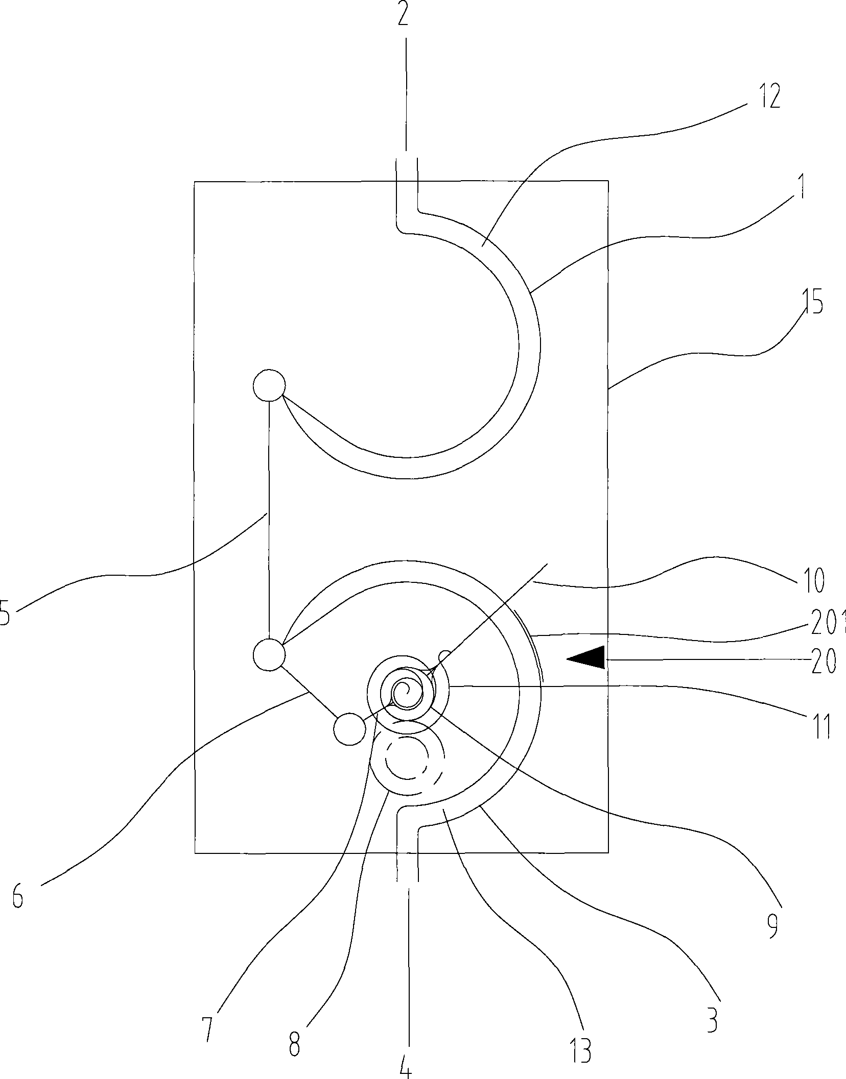
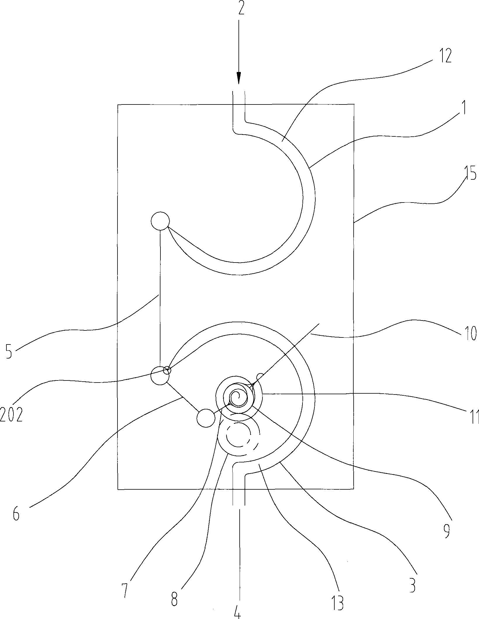
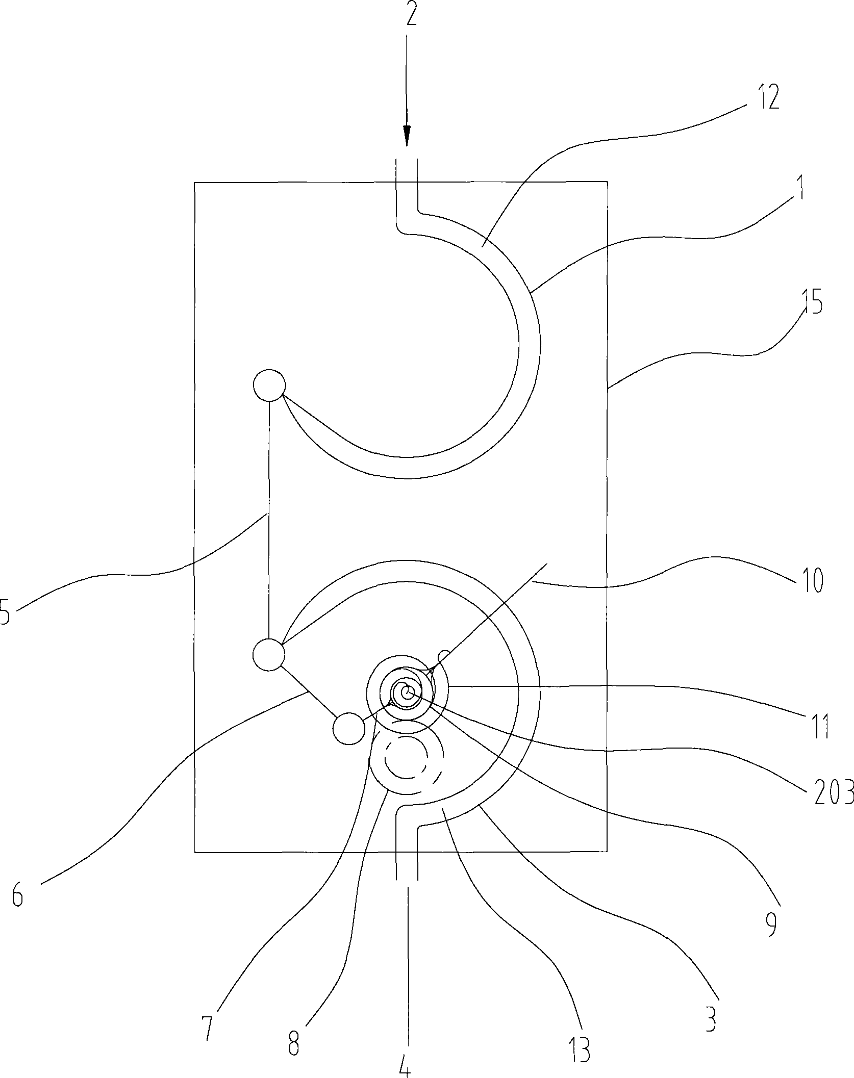
[0022] Preferred embodiments of the present invention will be described in detail below with reference to the accompanying drawings.

[0023] figure 1 A schematic structural diagram of a differential pressure sensor according to a first preferred embodiment of the present invention is shown. In this embodiment, the differential pressure sensor includes a package housing 15; first and second sensing elements 1, 3 and their first and second chambers 12, 13 respectively, the first chamber 12 has a The first pressure port 2 communicated, the second chamber 13 has a second pressure port 4 communicated with the outside world; used to transmit the deformation of the sensing elements 1, 3, amplified deformation transmission and amplification components; used to indicate the pressure a changing pointer 10; and a spring 11 for returning the pointer 10. In addition, the first and second pressure ports 2 and 4 are respectively used to connect with one test end of the container under tes...


PUM


Abstract

The invention discloses a differential meter, comprising a sealed shell, a first sensing element, a second sensing element, two cavities respectively surrounded by the two sensing elements, a long connecting bar, a short connecting bar, a swing stem and a gear cluster which are used for transmitting and amplifying the deformation of the sensing elements, a pointer used for indicating pressure change and a spring which can lead the pointer to reset. The differential meter also comprises a deformation sensing device used for sensing the deformation of the first sensing element or the second sensing element. The differential meter has two output ways of mechanical header display and electric signal output, thus being capable of feedbacking the pressure difference of a container and a device to be measured to an electric control system and facilitating industrial control; in addition, not only static pressure is increased but also the manufacturing process is simplified.

Description

technical field [0001] The invention relates to a pressure measuring device, in particular to a differential pressure sensor for pressure differential control. Background technique [0002] In industries such as electrical engineering and instrumentation, it is often required to control the pressure difference of containers and equipment. At this time, differential pressure sensors are often used. At present, in the preparation of differential pressure sensors, most of the elastic sensitive elements in them use Bourdon tubes, bellows and diaphragms. For Bourdon tube type and bellows type differential pressure sensors, the positive and negative pressure chambers are the same elastic element, and the pressure acts on one side of the elastic element, so there is a problem of low static pressure during use. However, the structure of the diaphragm type differential pressure sensor is complicated, and the inside needs to be filled with oil and vacuumized, thus making the cost hig...

Claims


Application Information

Patent Timeline
Patent Type & Authority Applications(China)
IPC IPC(8): G01L13/02
Inventor 丁东胜王生彪
Owner ZHONGSHAN TIANYUAN VACUUM EQUIP TECH CO LTD
Why Eureka
Try Eureka