Light-reformable optical element and light source module thereof

A technology for optical components and light source modules, applied in optical components, optics, nonlinear optics, etc., can solve the problems of general products without structure, no mention of light uniformity, and inability to change the emitted light, so as to improve luminous efficiency, Improve utilization and optimize the effect of light pattern

Inactive Publication Date: 2009-06-17
PRODISC TECH INC
View PDF5 Cites 3 Cited by
  • Summary
  • Abstract
  • Description
  • Claims
  • Application Information

AI Technical Summary

Problems solved by technology

[0009] Among the above inventions, Taiwan Patent No. M296481 only discloses a lighting module that can change the circular illumination area to an elliptical illumination area; Taiwan Patent No. M290967 only discloses that it can improve light intensity and uniform light intensity The light source module disclosed in U.S. Patent No. 5,515,253 can only improve the uniformity of emitted light, and the light-receiving structure disclosed in U.S. Patent No. 7,172,319 cannot change the light type. There is also no mention of improved light uniformity
[0010] It can be seen that the above-mentioned existing optical elements and light source modules thereof obviously still have inconveniences and defects in structure and use, and need to be further improved urgently.
In order to solve the above-mentioned problems, the relevant manufacturers have tried their best to find a solution, but for a long time no suitable design has been developed, and the general products do not have a suitable structure to solve the above-mentioned problems. This is obviously related The problem that the industry is eager to solve

Method used


Image

  • Light-reformable optical element and light source module thereof
  • Light-reformable optical element and light source module thereof
  • Light-reformable optical element and light source module thereof

Examples


Embodiment Construction

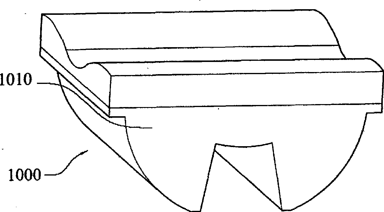
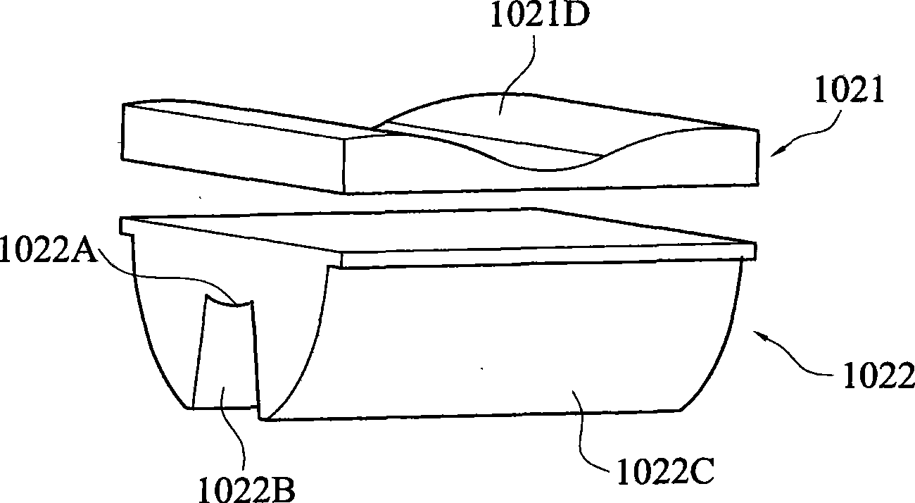
[0069] In order to further explain the technical means and effects of the present invention to achieve the intended purpose of the invention, the details of the optical element and its light source module that can be reconfigured according to the present invention are described below in conjunction with the accompanying drawings and preferred embodiments. Embodiments, structures, features and effects thereof are described in detail below.

[0070] The aforementioned and other technical contents, features and effects of the present invention will be clearly presented in the following detailed description of preferred embodiments with reference to the drawings. Through the description of specific embodiments, when the technical means and effects of the present invention are adopted to achieve the intended purpose, a more in-depth and specific understanding can be obtained, but the accompanying drawings are only for reference and description, and should be understood as the presen...


PUM


Abstract

The invention relates to an optical element capable of readjusting light shape and a light source module thereof. The optical element comprises a lens unit and is provided with a first area and a second area; wherein the first area is used for adjusting the light shape of a first direction; the second area is used for adjusting the light shape of a second area; the included angle between the first direction and the second direction is 70 degrees to 110 degrees. The light source module comprises a plurality of luminous elements and a plurality of lens units; wherein the lens units are arranged in an array mode and correspondingly arranged on the luminous element; the lens units are provided with a first area and a second area; the first area adjusts the emergent light shape of the first direction of the luminous elements, the second area adjusts the emergent light shape of the second direction of the luminous elements and the included angle between the first direction and the second direction is 70 degrees to 110 degrees; overall emergent light shape of a lens unit array is the sum of the emergent light shapes of all lens units. The lens units and the luminous elements can be arranged in an array mode to form the light source module; the overall emergent light shape and light shape area is the sum of the emergent light shape of the single lens unit. The invention can readjust the light shape, improve utilization rate of incoming ray and enhance light uniformity on illuminated area.

Description

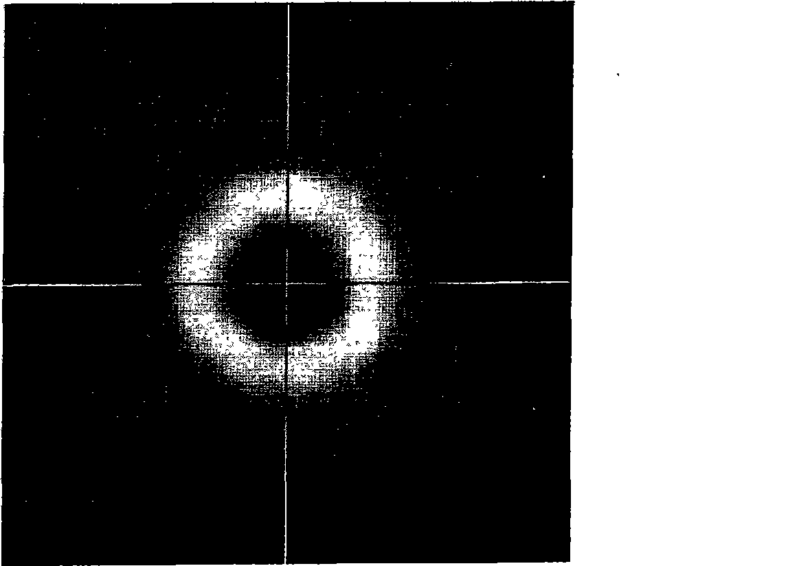
technical field [0001] The present invention relates to an optical element and its light source module, in particular to an optical element capable of reforming the light type, improving the utilization rate of incident light, and increasing the uniformity of light on the illuminated area. and its light source module. Background technique [0002] see figure 1 As shown, it is a schematic diagram of the light pattern of an existing traditional light source, in order to show the light pattern distribution of the traditional LED light source, the light source has the following disadvantages due to the light pattern distribution, including the discovery that the energy is too concentrated in the center and the light is uniform on the illuminated area The brightness is not good, and the illuminance will decrease in the corner; in addition, because the illumination area distribution of this light source is not rectangular, it is not suitable for road lighting; in addition, the la...

Claims


Application Information

Patent Timeline
Patent Type & Authority Applications(China)
IPC IPC(8): G02B3/00G02B1/10G02F1/13357F21V5/04
Inventor 曹志任
Owner PRODISC TECH INC
Why Eureka
Try Eureka