Automatic conveying device for compact wafer

An automatic transmission and compact technology, applied in the direction of transportation and packaging, conveyor objects, etc., can solve the problem of reducing the overall height, etc., to achieve the effect of reducing the overall height and width, stable transmission operation, and compact structural design

Active Publication Date: 2009-06-17
SHANGHAI FORTREND TECH CO LTD
View PDF7 Cites 9 Cited by
  • Summary
  • Abstract
  • Description
  • Claims
  • Application Information

AI Technical Summary

Problems solved by technology

[0013] The purpose of the present invention is to provide a compact wafer automatic transfer device, which can effectively overcome its structural limitations and cannot be applied in addition to inheriting the advantages of providing a clean microenvironment from the isolation technology in the SMIF in the prior art. Due to the shortcomings of complex actions in the narrow space of the process equipment, the structure design of the device is more compact, and its overall height is significantly reduced, leaving more operating space for the process equipment. The transmission operation is more stable, and the action is more flexible and reliable. Further expansion The scope of application is widened, so that it can realize the flipping of the wafer cassette in the range of 0-90 degrees in the limited stroke space, and set the tilt angle at will, so as to complete the automatic transmission of the wafer in the horizontal or vertical state, and at the same time realize the wafer cassette Translate left and right to adapt to automatic transmission in a narrow space where the center distance of process equipment arranged side by side is smaller than the center distance of transmission equipment, and it can be flexibly stopped when encountering external interference to achieve a precisely controlled transmission effect

Method used


Image

  • Automatic conveying device for compact wafer
  • Automatic conveying device for compact wafer
  • Automatic conveying device for compact wafer

Examples


Embodiment Construction

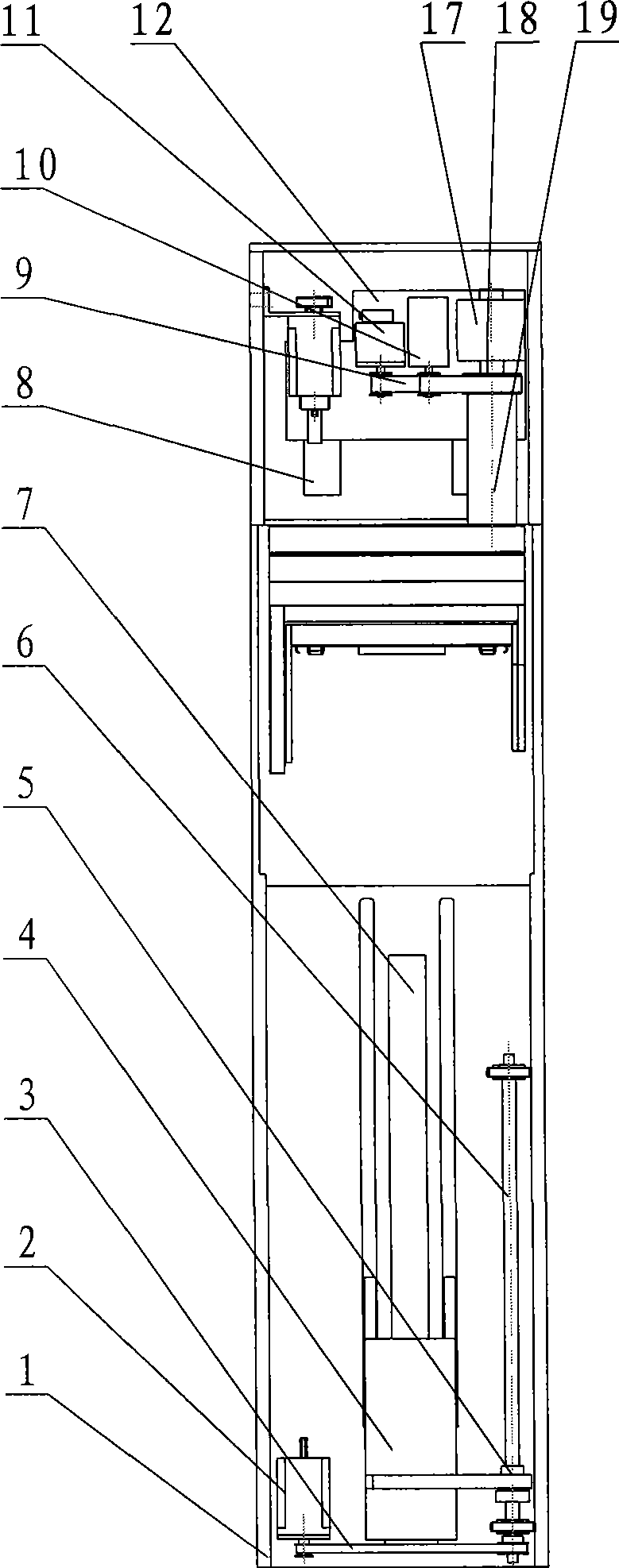
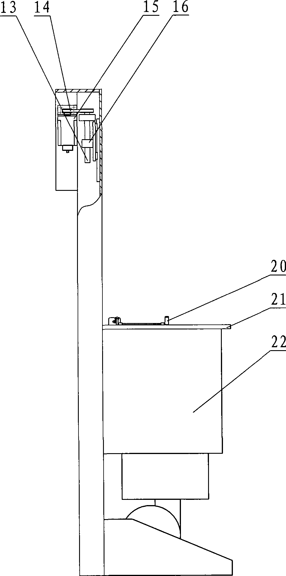
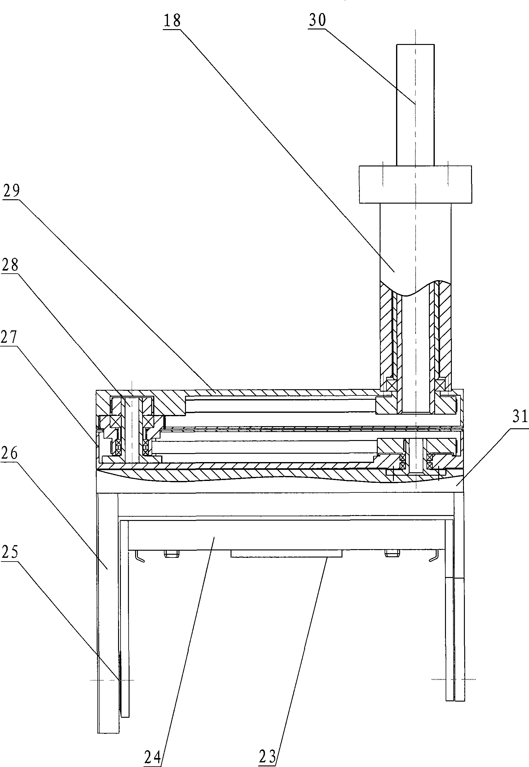
[0035] according to Figure 1-10 The specific structure of the present invention will be described in detail. The flip-type wafer automatic transfer device is based on the advantages of patented technologies such as "a method of delivering wafers for IC manufacturing" in US Patent 6,086,323, and is redesigned according to the defects in the prior art. It includes a frame 1, a feeding platform 21 fixed on the frame 1, a bellows body 22 with a claw mechanism 20 assembled on the frame 1 for lifting and moving, and a bellows body 22 with a claw mechanism 20 for lifting and extending movement. The arm mechanism 19 etc. of mechanism 24. Wherein the wind box body 22 is an integrated air filtration system, which can provide a clean microenvironment. Its working principle is basically the same as the method in the above-mentioned US patent technology, and will not be repeated here.

[0036] Such as figure 1 , 2 As shown, the bellows body 22 is assembled on the bellows body fixing ...


PUM


Abstract

A compact wafer automatic transmitting device overcomes shortages that the prior art can not do complicated actions in a narrow space in a processing procedure and the like, which comprises a framework, a material loading platform, a wind chest body and an arm mechanism. The technical key includes that a lifting motor and an extending motor are not arranged on an identical plane, a lower arm is connected with a catching mechanism through a translating mechanism and a turnover mechanism, the catching mechanism is driven by a geared linkage driving mechanism to rotate around a shaft line, a catching motor of the catching mechanism drives a holding jaw to reciprocate, and a locating mechanism on the catching mechanism can be equipped with an adjustable locating block. The compact wafer automatic transmitting device is reasonable in design, stable in operation when transmitting during the processing procedure, and flexible and reliable in action, completes automatic transmitting of wafers in horizontal or perpendicular state in a limited travel space, simultaneously realizes left and right translating and turnover of a wafer cassette to be suitable for totally realizing automatic transmitting in a narrow space in which center distances of process equipment which are in parallel arrangement are smaller than the center distance of the transmitting device, and can flexibly stop when encountering interference of outsides, thereby achieving transmitting effect of accurate control.

Description

technical field [0001] The invention relates to a wafer conveying device. In particular, the structural design for loading and unloading Standard Mechanical Interface (SMIF) wafer cassettes is more compact, significantly reducing its overall height, and leaving more room for process equipment in the limited travel space. The operating space further expands the applicable range of compact automatic wafer transfer devices. Background technique [0002] Currently, in the semiconductor manufacturing process, wafer handling is critical to IC manufacturing. In order to ensure the quality of wafers when they are transported between different processes and avoid dust particles or other contamination of wafers, more and more transport work uses standard transport containers, that is, standard mechanical interface (SMIF for short) )technology. For example, in US Patents 4,532,970 and 4,534,389, a SMIF system is disclosed. The system reduces the contamination of the wafer by dust p...

Claims


Application Information

Patent Timeline
Patent Type & Authority Applications(China)
IPC IPC(8): H01L21/677
Inventor 吴功
Owner SHANGHAI FORTREND TECH CO LTD
Why Eureka
Try Eureka