Bandpass filter, high-frequency module using the same, and radio communication device using them

A band-pass filter and band-shaped technology, which is applied in the field of wireless communication equipment and band-pass filter, can solve problems such as unusable, excessively wide passband, and narrow passband

Active Publication Date: 2013-01-02
KYOCERA CORP
View PDF2 Cites 0 Cited by
  • Summary
  • Abstract
  • Description
  • Claims
  • Application Information

AI Technical Summary

Problems solved by technology

Therefore, the passband width disclosed in the non-patent literature is a bandpass filter having characteristics exceeding 100% of the band width, and the passband width is too wide to be used.
[0008] In addition, the passband of the bandpass filter using the 1 / 4 wavelength resonator in the prior art is too narrow. The ratio band domain is also less than 10%
Therefore, it cannot be used as a bandpass filter for UWB that requires a ratio band equivalent to 30% or more
[0009] Furthermore, in the bandpass filter disclosed with reference to JP-A-11-88009, an attenuation pole can only be generated on either the low-band side or the high-band side compared with the passband, so it cannot be used as necessary. It is used as a bandpass filter for UWB with sharp attenuation on both sides of the passband

Method used


Image

  • Bandpass filter, high-frequency module using the same, and radio communication device using them
  • Bandpass filter, high-frequency module using the same, and radio communication device using them
  • Bandpass filter, high-frequency module using the same, and radio communication device using them

Examples


no. 1 Embodiment approach

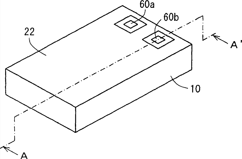
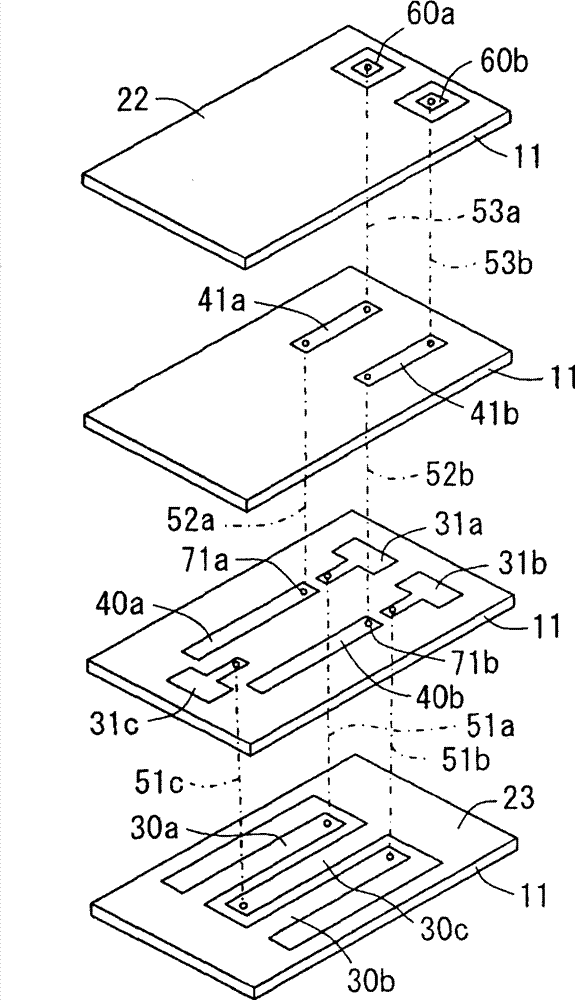
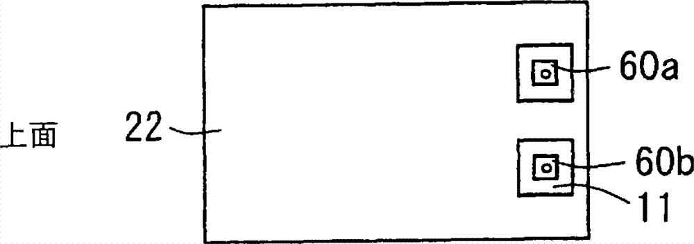
[0115] figure 1 It is a perspective view schematically showing the appearance of the bandpass filter according to the first embodiment of the present invention. figure 2 yes figure 1 A schematic exploded perspective view of the bandpass filter shown. Figure 3A ~ Figure 3E is a schematic representation figure 1 A plan view of the upper and lower sides and between layers of the bandpass filter shown. Figure 4 yes figure 1 A1~A1' line sectional drawing.

[0116] The bandpass filter of this embodiment is composed of the following components: a laminate 10 in which a plurality of dielectric layers 11 are stacked; a first ground electrode 21 arranged on the lower surface of the laminate 10; a second ground electrode 21 arranged on the upper surface of the laminate 10 Electrode 22; strip-shaped resonant electrodes 30a, 30b, 30c arranged laterally in the interlayer A of the laminated body 10; ring-shaped resonant electrodes 30a, 30b, 30c surrounded by the interlayer A of the l...

no. 2 Embodiment approach

[0137] 5 is a perspective view schematically showing the appearance of a bandpass filter according to a second embodiment of the present invention. Figure 6 is a schematic exploded perspective view of the bandpass filter shown in FIG. 5 . Figure 7A ~ Figure 7F It is a plan view schematically showing the upper and lower surfaces and between layers of the bandpass filter shown in FIG. 5 . Figure 8 It is a sectional view along line A1 to A1' in Fig. 5 . In addition, in this embodiment, only the differences from the first embodiment will be described, and the same components will be given the same reference numerals, and will not be described again.

[0138] The characteristic part of the bandpass filter of this embodiment is that, for the interlayer A where the resonant electrodes 30a, 30b, 30c and the ring-shaped ground electrode 23 are arranged, the interlayer B where the auxiliary resonant electrodes 31a, 31b, 31c are arranged In the interlayer D on the opposite side, the...

no. 3 Embodiment approach

[0142] Figure 9 It is a perspective view schematically showing the appearance of the bandpass filter according to the third embodiment of the present invention. Figure 10 yes Figure 9 A schematic exploded perspective view of the bandpass filter shown. Figure 11A ~ Figure 11H is a schematic representation Figure 9 A plan view of the upper and lower sides and between layers of the bandpass filter shown. Figure 12 yes Figure 9 A1~A1' line sectional drawing. In addition, in this embodiment, only the differences from the above-mentioned embodiments will be described, and the same components will be assigned the same symbols, and will not be described again.

[0143] The characteristic part of the band-pass filter of this embodiment is that, for the layer C where the auxiliary input coupling electrode 41a and the auxiliary output coupling electrode 41b are arranged, the input coupling electrode 40a, the output coupling electrode 40b, and the auxiliary resonant electrode ...


PUM


Abstract

The present invention relates to a bandpass filter having a passband passband width appropriate as a bandpass filter for UWB, a high frequency module using the bandpass filter, and a radio communication device using the bandpass filter and the high frequency module. There is provided a bandpass filter including a laminate composed of a plurality of dielectric layers 11; first and second ground electrodes arranged on the bottom and top surfaces, respectively, of the laminate; resonance electrodes 30a, 30b, and 30c arranged in an inter-digital type on a first inter-layer portion of the laminate, one end of each of the resonance electrodes being grounded; an input coupling electrode 40a arranged on an inter-layer portion different from the first inter-layer portion of the laminate to face the resonance electrode 30a of the input stage in the inter-digital type; and an output coupling electrode 40b arranged on an inter-layer portion different from the first inter-layer portion of the laminate to face the resonance electrode 30b of the output stage. Accordingly, it can be possible to achieve a bandpass filter that has a flat and low-loss transmission characteristicstransmission characteristic over the entire region of the broad pass bandpassband that could not be achieved by a bandpass filter using the conventional 1 / 4 wavelength resonator.

Description

technical field [0001] The present invention relates to a bandpass filter, a high frequency module using it and a wireless communication device using them, especially a bandpass filter with a very wide passband suitable for use in UWB (Ultra Wide Band), using it high-frequency modules and wireless communication devices using them. Background technique [0002] In recent years, UWB has attracted attention as a new communication unit. UWB is a technology that realizes large-capacity data transmission using a wide frequency band in a short distance of about 10 m. For example, it is planned to use a frequency band of 3.1 to 10.6 GHz according to regulations of the FCC (Federal Communication Commission) of the United States. Thus, UWB is characterized by using a very wide frequency band. In Japan and ITU-R, in order to avoid the 5.3GHz used in IEEE802.11.a, it is divided into LowBand (low band) using a band of about 3.1-4.7GHz and a band using about 6GHz-10.6GHz The HighBand ...

Claims


Application Information

Patent Timeline
Patent Type & Authority Patents(China)
IPC IPC(8): H01P1/203H01P1/205
Inventor 吉川博道
Owner KYOCERA CORP
Why Eureka
Try Eureka