Steam heating device for cloth roller of beam dyeing machine

A technology of steam heating device and cloth rolling roller, which is applied in textile processing machine accessories, equipment configuration for processing textile materials, liquid/gas/steam open-width fabric processing, etc. It can solve the problems of head and tail color difference, and achieve the elimination of head and tail color difference , to solve the effect of temperature difference

Inactive Publication Date: 2009-06-24
靖江市华信科技创业园有限公司
View PDF6 Cites 14 Cited by
  • Summary
  • Abstract
  • Description
  • Claims
  • Application Information

AI Technical Summary

Problems solved by technology

The dyeing bath ratio of the commonly used overflow jet dyeing machine is about 1:20, that is, 1 kg of cloth (fabric) needs to be dyed with 20 kg of dye solution (most of which is water, and water accounts for about 99.98% of the dye solution). The dyeing bath ratio of the jigger is only about 1:3, and the lowest can be less than 1:2. Compared with the overflow jet dyeing machine, it can save a lot of energy consumption, mainly coal, electricity, and water consumption. At the same time Dyeing sewage discharge is only about one-tenth of the overflow jet dyeing machine. It is an energy-saving and environmentally friendly dyeing machine. Part of the dyeing temperature is different, mainly because the two cloth rollers are above the dye liquor, which is always lower than the temperature of the dye liquor. The higher the dyeing temperature, the greater the temperature difference between the dye liquor and the cloth rollers, which makes the cloth on the rollers The temperature of the cloth close to the roll is lower than that of other places, so the color of the cloth close to the roll gradually becomes lighter, resulting in a situation where the entire dyed fabric is dark in the middle and light at both ends.

Method used


Image

  • Steam heating device for cloth roller of beam dyeing machine
  • Steam heating device for cloth roller of beam dyeing machine

Examples


Embodiment Construction

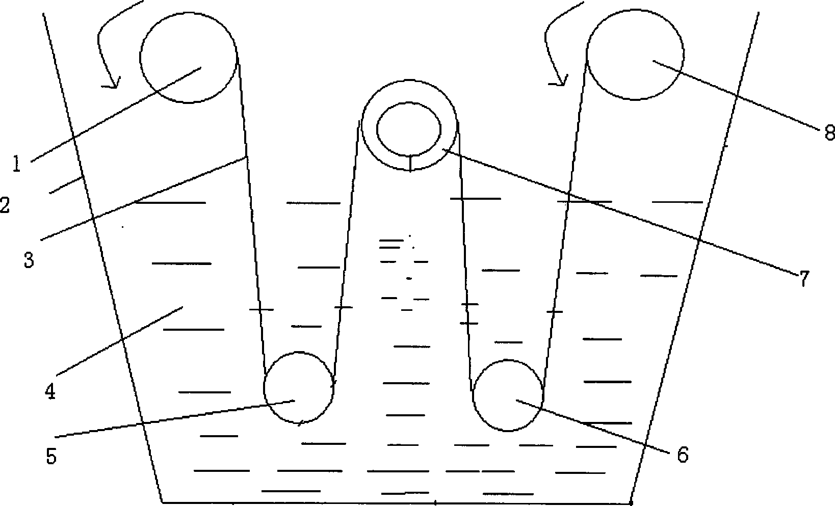
[0010] figure 1 It is a schematic diagram of the dyeing structure of a jigger in the prior art. The jigger includes a housing 2 in which the dye solution is located. It also includes a first cloth roll 1 and a second cloth roll 8 located at the upper end of the liquid surface. The first lower roller 5 and the second lower roller 6 inside the dye liquor are located between the first lower roller 5 and the second lower roller 6 and above the first lower roller 5 and the second lower roller 6 The force measuring roller 7, the pre-processed fabric 3 is rolled onto the second cloth roll 8, and then the cloth head passes through the second lower roller 6, the force measuring roller 7, and the first lower roller 5 to the first cloth roller 1 on.

[0011] When dyeing starts, the first cloth roll 1 rotates counterclockwise, and the first lower roller 5 and the second lower roller 6 are driven by the cloth. The force measuring roller 7 and the second cloth roller 8 rotate to make the clot...


PUM


Abstract

The invention discloses a steam heating device for a cloth roller of a jig dyeing machine. The invention is characterized in that the device comprises a cloth roller ring-shaped heating cavity arranged inside a cloth roller crust, a steam inlet revolving joint and a steam outlet revolving joint are respectively arranged at the two sides of the cloth roller crust, a steam inlet hole which can be connected with the cloth roller ring-shaped heating cavity and the steam inlet revolving joint is arranged on a cloth roller inner core, a steam inlet tube is connected with the steam inlet revolving joint, a control system which is used to measure the temperature of the cloth roller crust and control the quantity of steam entering the cloth roller ring-shaped heating cavity according to the measured temperature. The steam heating device in the invention solves the problem that temperature difference exists between the cloth roller and the dyeing solution, thus eliminating the color deviation between initial dyeing of the cloth and the final dyeing of the cloth.

Description

Technical field [0001] The invention relates to a steam heating device for a cloth winding roller of a jigsaw dyeing machine, which belongs to the textile printing and dyeing machinery industry. Background technique [0002] The printing and dyeing industry is an industry with high energy consumption and high pollution. Therefore, the development of dyeing machines with low energy consumption and low emissions is the goal of the printing and dyeing machinery manufacturing industry. The dyeing bath ratio of the commonly used overflow jet dyeing machine is about 1:20, that is, 1 kilogram of cloth (fabric) needs 20 kilograms of dye liquor (most of which is water, and water accounts for about 99.98% of the dye liquor) for dyeing. The dyeing bath ratio of the jig dyeing machine is only about 1:3, and the lowest is less than 1:2. Compared with the overflow jet dyeing machine, it can save a lot of energy consumption, which mainly consists of the consumption of coal, electricity and wate...

Claims


Application Information

Patent Timeline
Patent Type & Authority Applications(China)
IPC IPC(8): D06B23/22D06B23/00D06B3/32
Inventor 张同生
Owner 靖江市华信科技创业园有限公司
Why Eureka
Try Eureka