
Cooling system of engine

An engine cooling and oil cooler technology, which is applied in the direction of engine cooling, engine components, machines/engines, etc., can solve the problems such as the inability to meet the engine warm-up requirements and the branch circuit can not meet the flow requirements, so as to improve fuel economy. , Improve the cooling effect, improve the effect of temperature control accuracy

Active Publication Date: 2009-06-24
CHERY AUTOMOBILE CO LTD
View PDF2 Cites 24 Cited by
  • Summary
  • Abstract
  • Description
  • Claims
  • Application Information

AI Technical Summary

Problems solved by technology

Although these methods can improve the warm-up effect of the engine to a certain extent, as the national emission regulations become more and more stringent, the use of these technologies alone cannot meet the warm-up requirements of the engine.
In addition, with the use of various new technologies, many components need to be cooled to work effectively. If the layout is unreasonable, some branches will not meet the flow requirements.

Method used


Image

  • Cooling system of engine
  • Cooling system of engine
  • Cooling system of engine

Examples


Embodiment Construction

[0021] The present invention will be specifically described below in conjunction with the accompanying drawings.

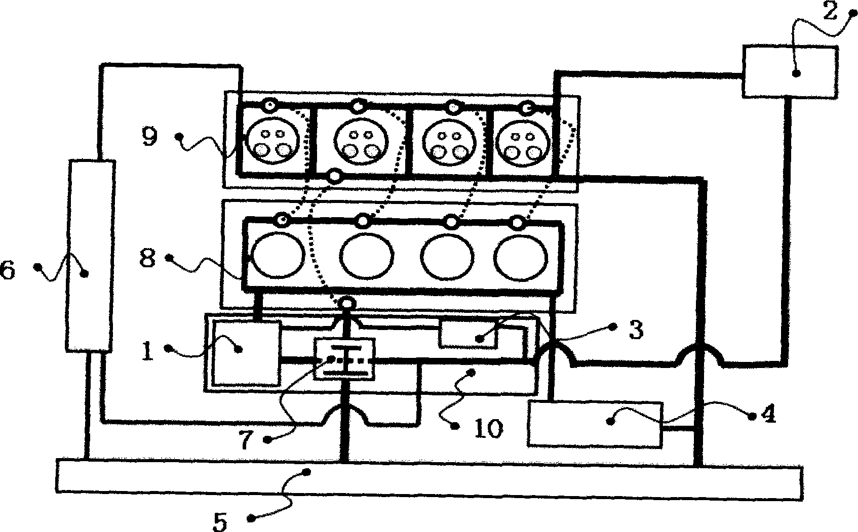
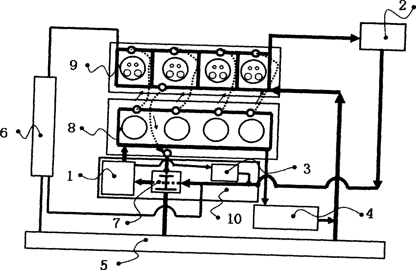
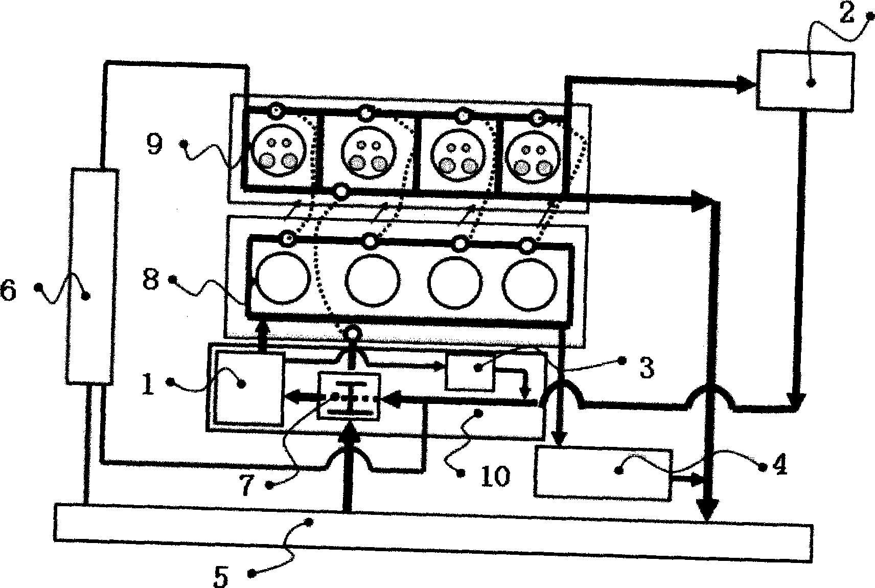
[0022] figure 1 Shown is a schematic diagram of the engine cooling system layout. The entire engine cooling system includes water pump 1, heater 2, oil cooler 3, EGR cooler 4, radiator 5, expansion tank 6, thermostat 7, cylinder block water jacket 8, cylinder head water jacket 9 and integrated bracket 10 . The water pump 1, the oil cooler 3 and the thermostat 7 are installed on the integrated bracket 10, and the thermostat 7 adopts a water inlet arrangement, which can improve the temperature control accuracy of the engine coolant. The cylinder body water jacket 8 is connected with the cylinder head water jacket 9 through the cylinder head water inlet on the cylinder gasket. A water pump vortex chamber is cast on the integrated bracket 10, and the coolant flows from the water outlet on the integrated bracket 10 to the cylinder water jacket 8 through the water pu...


PUM


Abstract

The invention discloses an engine cooling system, comprising a pump (1), a heater unit (2), an oil cooler (3), an EGR cooler (4), a radiator (5), an expansion tank (6), a thermolator (7), a cylinder body water jacket (8), a cylinder head water jacket (9) and an integrated support (10), wherein, the pump (1), the oil cooler (3) and the thermolator (7) are mounted on the integrated support (10), and the thermolator (7) is a high purity wax thermolator which is arranged at a water inlet; cooling fluid entering the cylinder head water jacket (9) flows out through the back end of the cylinder head, two water outlets are arranged at two sides of the back end of the cylinder head, the water outlet at the air inlet side is connected with the radiator (5), the water outlet at the air outlet side is connected with the heater unit (2), a branch circuit of the heater unit is normally open, and the branch circuit of the heater unit is controlled by the thermolator (7). By increasing the initial operating temperature and lowering the temperature difference between the full operating temperature and the initial operating temperature, the engine cooling system of the invention can improve cooling effect, thus improving economical efficiency of engine gas fuel, and lowering discharge of harmful gases; in addition, the structural arrangement is more compact.

Description

technical field [0001] The invention belongs to the field of passenger cars, in particular to a cooling system for a water-cooled engine of a passenger car. Background technique [0002] In the existing engine cooling system, the coolant is generally directly pumped into the engine cylinder through a water pump, enters the cylinder head from the upper water port of the cylinder gasket, and then comes out from the cylinder head, and a double valve is installed at the water outlet of the cylinder head Wax-type thermostat, the thermostat controls the opening and closing of large and small cycles according to the temperature of the coolant. The thermostat is generally arranged at the water outlet of the engine. At the same time, because the temperature difference between the full opening temperature and the initial opening temperature is too large, the temperature difference can reach 15°C, and the temperature control of the thermostat is very inaccurate. , It is easy to cause ...

Claims


Application Information

Patent Timeline
IPC IPC(8): F01P7/16
Inventor 易书林解正斌
Owner CHERY AUTOMOBILE CO LTD
Learn More