Non-welded plate type heat exchanger

A plate heat exchanger, non-welded technology, applied in indirect heat exchangers, heat exchanger types, fixed plate conduit assemblies, etc., can solve the problems of complex manufacturing process, poor heat transfer efficiency, complex structure, etc., and achieve a simple structure. Compact, improved service life, good heat transfer performance

Active Publication Date: 2009-06-24
LUOYANG RUICHANG PETROCHEM EQUIP
View PDF0 Cites 11 Cited by
  • Summary
  • Abstract
  • Description
  • Claims
  • Application Information

AI Technical Summary

Problems solved by technology

[0003] In order to overcome the deficiencies of the prior art, the present invention discloses a non-welded plate heat exchanger. The equipment has the advantages of simple and compact structure, easy processing and manufacture, low cost, easy mass production, tight sealing and high heat transfer efficiency. Wide range, small pressure drop, etc., can effectively solve technical problems such as complex manufacturing process, complex structure, high price, large pressure drop, and poor heat transfer efficiency in existing heat transfer equipment

Method used


Image

  • Non-welded plate type heat exchanger
  • Non-welded plate type heat exchanger
  • Non-welded plate type heat exchanger

Examples


Embodiment 1

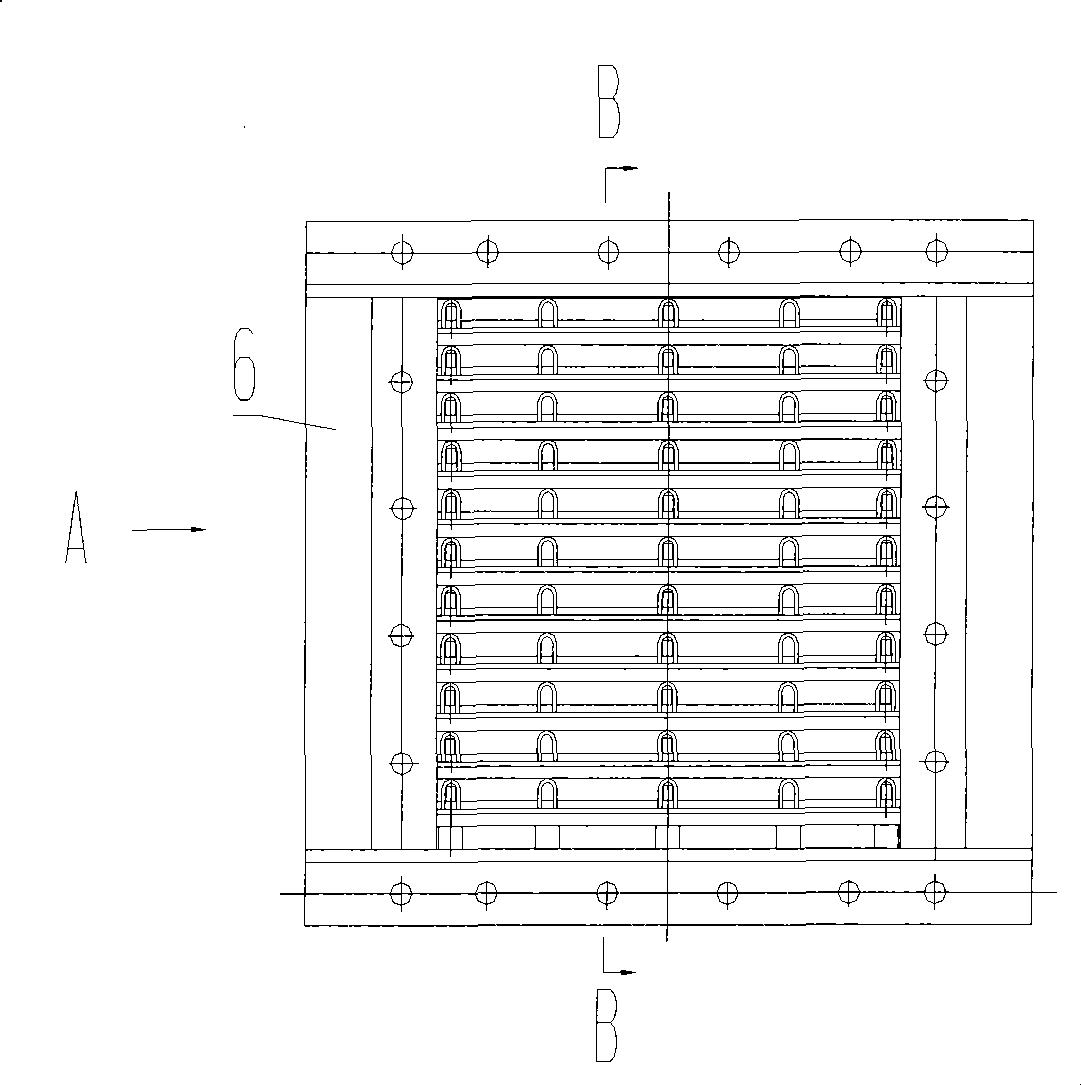
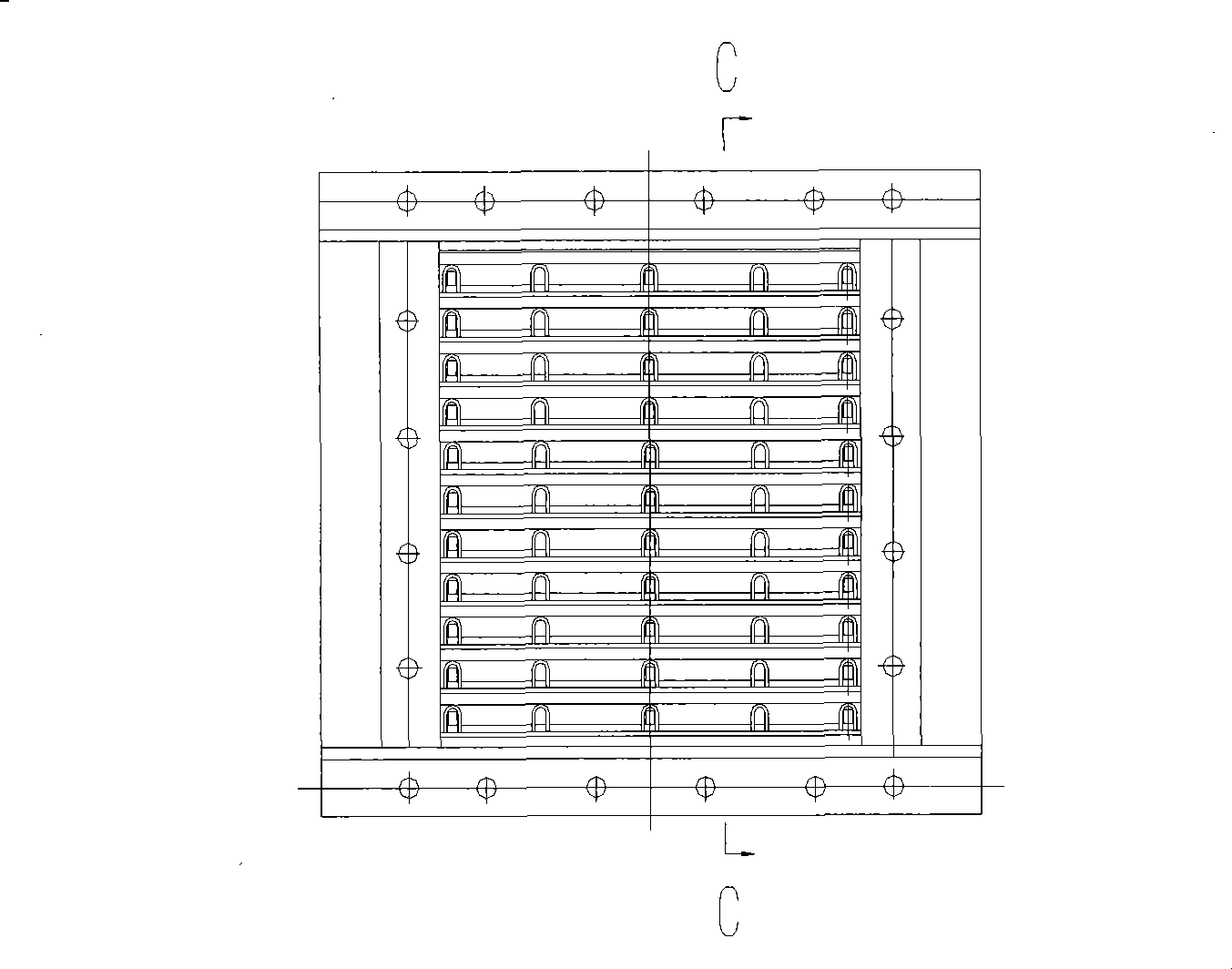
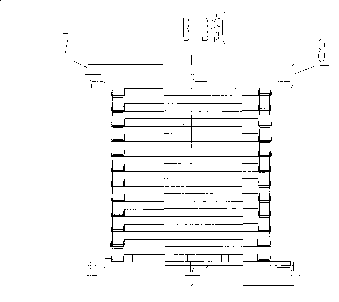
[0028] Embodiment 1: A non-welded plate heat exchanger, consisting of a plurality of heat exchange plates 1 placed up and down staggered to form a plurality of fluid channels, the openings of the adjacent fluid channels in the plurality of fluid channels are staggered by 90°, respectively A hot fluid channel and a cold fluid channel are formed; the hot fluid channel has a hot fluid inlet flange 7 and a hot fluid outlet flange 8, and the cold fluid channel has a cold fluid inlet flange 9 and a cold fluid outlet flange 10; the heat exchange plate Sheet 1 is made of rectangular stainless steel sheet. The above-mentioned components are located in the frame welded by the upper cover plate 11 , the lower cover plate 12 and the column 6 . A sealing gasket 5 is placed between the folded fins of the adjacent upper and lower heat exchange plates 1, and the sealing gasket 5 is a flexible graphite plate; an elastic bead 3 is arranged between two adjacent heat exchange plates , the elasti...

Embodiment 2

[0033] The heat exchange plates 1 are made of rectangular aluminum plates.

[0034] The sealing gasket 5 placed between the hemming fins of the adjacent upper and lower heat exchange plates 1 is a ceramic fiber sealing gasket.

[0035] All the other technical solutions are the same as in Example 1.

Embodiment 3

[0037] The heat exchange plate 1 adopts the structure of coating a layer of enamel on the surface of the metal plate, so as to achieve the purpose of anticorrosion.

[0038] The heat exchange plate 1 can also be a metal plate with corrugations processed on the plate surface, so as to achieve the purpose of improving heat transfer efficiency.

[0039] Several turbulent elements are arranged between the heat exchange plates, so as to achieve the purpose of improving heat transfer efficiency. The turbulence element is a cross zigzag belt and twisted iron.

[0040] All the other technical solutions are the same as in Example 1.


PUM


Abstract

The invention relates to the technology of heat exchangers, particularly a weldless plate-type heat exchanger. A plurality of fluid passages are formed by a plurality of heat exchange plates 1 which are vertically placed in a rectangularly (90 DEG) staggered manner, wherein, the openings of adjacent fluid passages among the fluid passages are mutually staggered at an angle of 90 DEG to form hot fluid passages and cold fluid passages; upward right-angled fold edges are formed on the two symmetric sides of each heat exchange plate 1, and right-angled double-fold edges are formed on the other two corresponding sides so as to form L-shaped fold edges; each two vertically adjacent heat exchange plates are placed in a rectangularly (90 DEG) staggered manner, that is, the downward L-shaped fold edge of an upper heat exchange plate is correspondingly placed between the upward right-angled fold edges of a lower heat exchanges plate, and the upward rectangular (90 DEG) fold edge of the lower heat exchange plate serves the function of limiting to the L-shaped fold edge of the upper heat exchange plate; a sealing gasket 5 is arranged between the lower heat exchange plate and the upper exchange plate; a flexible sealing layering 3 is arranged between each two adjacent heat exchange plates; and a support strip 2 is arranged between the passage formed by the upper heat exchange plate and thelower heat exchange plate.

Description

technical field [0001] The invention relates to heat exchanger technology, in particular to a non-welded plate heat exchanger, which is used for efficient heat transfer in oil refining, chemical industry, electric power, energy and other industries. Background technique [0002] Plate heat exchanger is an efficient and compact heat exchange equipment, which has many advantages such as high heat transfer coefficient, small pressure loss, compact structure, convenient maintenance, etc., and with the improvement of structure and the improvement of large-scale manufacturing technology, plate heat exchanger The application of the heater is paid more and more attention by people. However, due to the limitations of the traditional bulk plate heat exchanger (detachable plate heat exchanger), the operating pressure does not exceed 2.5MPa, the operating temperature does not exceed 250°C, the maximum assembly area is 2000m2, and there are rubber seals The defect that the pad is prone ...

Claims


Application Information

Patent Timeline
Patent Type & Authority Applications(China)
IPC IPC(8): F28D9/00
Inventor 邵松程高锋吕凤王伟马晓阳乔亮
Owner LUOYANG RUICHANG PETROCHEM EQUIP
Why Eureka
Try Eureka