
Displacement or acceleration sensor

An acceleration sensor and displacement technology, applied in the direction of acceleration measurement, instruments, and measuring devices using inertial force, can solve the problems of high demodulation costs, etc., and achieve the effects of mature demodulation technology, removal of temperature crosstalk, high sensitivity and precision

Inactive Publication Date: 2009-06-24
DALIAN UNIV OF TECH
View PDF1 Cites 11 Cited by
  • Summary
  • Abstract
  • Description
  • Claims
  • Application Information

AI Technical Summary

Problems solved by technology

This sensor also has the similar defects of the displacement sensor mentioned above, and its demodulation cost is expensive, which has a certain gap in the actual large-scale application

Method used


Image

  • Displacement or acceleration sensor
  • Displacement or acceleration sensor
  • Displacement or acceleration sensor

Examples


Embodiment 1

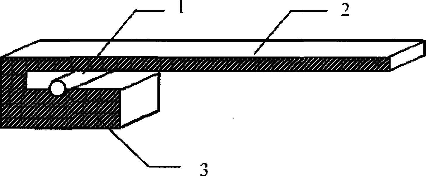
[0023] figure 1 In the above, the first fiber laser 1 is placed between the cantilever beam 2 and the first platform 3, and is in contact with the two. The material of the cantilever beam 2 can be: plastic, polymer material, metal plate, etc., when the end is subjected to force, displacement will occur, and at the same time, mechanical pressure will be exerted on the fiber laser below it. In this embodiment, a distributed Bragg reflective fiber laser (DBR fiber laser) is used, operating in a single longitudinal mode with dual polarization states, and the cantilever beam is made of plastic polymer. Those skilled in the art should understand that when the fiber laser is subjected to lateral pressure, the birefringence effect produced by the fiber will cause the polarization beat signal output by the fiber laser to change.

[0024] The relationship between the displacement (deflection) of the end of the cantilever beam and the pressure on the optical fiber is given by the follow...

Embodiment 2

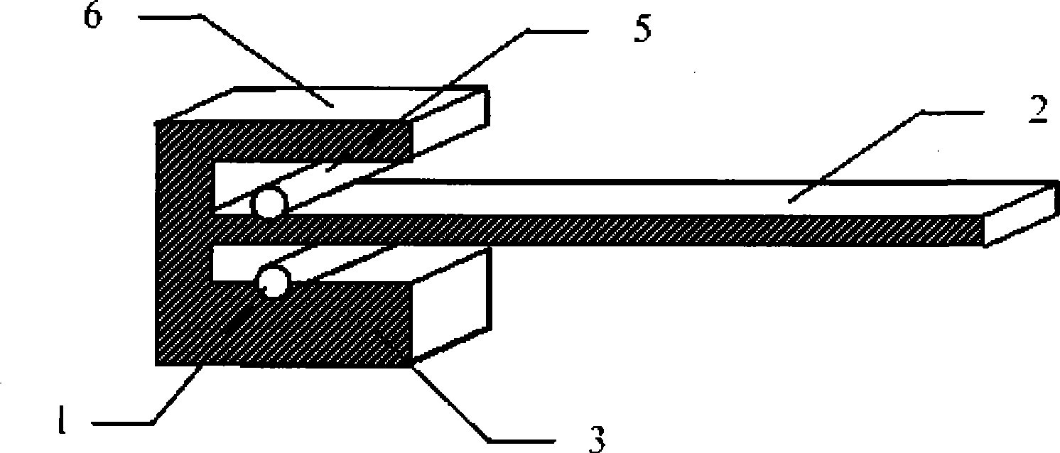
[0035] An acceleration sensor such as Figure 4 , the same characteristic structure of the above-mentioned displacement sensor can also be used to measure the acceleration parameter. When the cantilever beam 2 and the first fiber laser 1 are in an acceleration environment, the first fiber laser 1 will be subjected to the reaction force of the cantilever beam, thereby changing the polarization beat frequency signal of the output light of the first fiber laser 1 . By measuring the change of the polarization beat frequency signal, the environmental acceleration parameter can be obtained.

[0036] Those skilled in the art should understand that although the cantilever beam has a certain amplification effect as an acceleration sensor, since the acceleration is related to the mass, in order to obtain a larger inertial force, an inertial mass 4 can be fixed at the end of the cantilever beam to increase the sensitivity of the sensor , so this embodiment fixes a metal copper block at ...


PUM


Abstract

The invention discloses a displacement sensor or an acceleration sensor, belongs to the technical field of fiber sensors, and is characterized in that the displacement sensor or the acceleration sensor comprises a first fiber laser, a cantilever beam and a first platform, wherein, the first fiber laser is clamped between the surfaces of the cantilever beam and the first platform; the first fiber laser and the first platform are arranged below or above the cantilever beam; and the deformation generated by the cantilever beam generates acting force to the first fiber laser. The invention has the effects and benefits that the sensor overcomes the defect that the conventional electrical sensor is liable to electromagnetic interference; and the invention provides the fiber displacement sensor or the fiber acceleration sensor having the advantages of high sensitivity, large measurement range, simple structure, low demodulation cost and better signal-to-noise ratio.

Description

technical field [0001] The invention relates to the field of optical fiber sensing technology, in particular to a displacement or acceleration sensor based on a fiber laser, which can be used in the fields of micro-displacement monitoring of bridges, buildings, dams and other structures, earthquake monitoring, military micro-vibration measurement and the like. Background technique [0002] Displacement sensors are widely used in many fields such as industry, construction engineering, and offshore platform structure monitoring, and are very important sensors. Traditional displacement sensors are usually realized by electrical structures such as piezoelectric ceramics. Although the technology is mature and the cost is relatively low, it has many shortcomings such as low sensitivity, limited temperature range, and difficulty in shielding electromagnetic interference. [0003] With the rapid development of fiber optic devices in the 1990s, fiber optic sensors have developed into...

Claims


Application Information

Patent Timeline
Patent Type & Authority Applications(China)
IPC IPC(8): G01B11/02G01P15/03
Inventor 关柏鸥张扬
Owner DALIAN UNIV OF TECH
Learn More