
Vertical spray quenching apparatus and quenching technique

A technology of quenching equipment and vertical spraying, applied in the direction of quenching equipment, heat treatment equipment, manufacturing tools, etc., to achieve the effects of improving hardenability, shortening transfer time, and simple equipment structure

Active Publication Date: 2009-07-01
GRIMAT ENG INST CO LTD
View PDF0 Cites 7 Cited by
  • Summary
  • Abstract
  • Description
  • Claims
  • Application Information

AI Technical Summary

Problems solved by technology

Increasing the water flow velocity at which the water flow hits the surface of the alloy rod during quenching can break the vapor film generated during the quenching of the alloy, thereby effectively improving the hardenability of the alloy material, but there is no mandatory requirement for large-diameter alloy rods Report on Spray Quenching Equipment

Method used


Image

  • Vertical spray quenching apparatus and quenching technique

Examples


Embodiment 1

[0036] Embodiment 1 Vertical spray quenching equipment

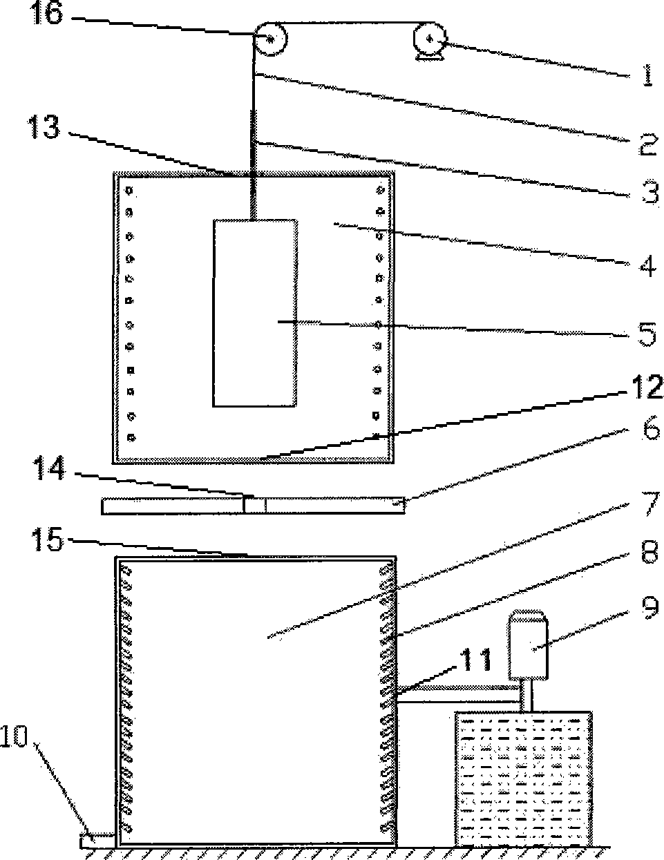
[0037] like figure 1 As shown, the device includes the following components: a heating chamber 4, which has a feed inlet 13 at the top and a discharge outlet 12 at the bottom; a water vapor isolation plate 6 is arranged under the heating chamber 4, and the isolation plate 6 can be opened in half. There is a circular hole 14 in the middle that is slightly larger than the inlet and outlet rods; below the isolation plate 6 is a spray quenching chamber 7, with a feed inlet 15 at the top, a water outlet 10 at the bottom, and a plurality of water nozzles 8 in the inner ring. The external water source is pressurized by the booster pump 9 and sprayed into the spray quenching chamber 7 through the water inlet 11 through the water nozzle 8; The alloy workpiece (not shown in the figure) is put into the loading hopper 5, and the motor 1 drives the feeding rod 3 and the loading hopper 5 to move up and down through the pulley 16 hois...

Embodiment 2

[0038] Example 2 Spray quenching process of aluminum alloy extruded rods

[0039] First put the 2D70 aluminum alloy extruded bar with a diameter of 250mm into the loading hopper 5, start the feeding motor 1, pass the steel wire rope 2, use the feeding rod 3 to place the workpiece at a suitable position in the heating chamber 4, and turn on the power supply of the heating chamber 4 Solution heat treatment is carried out.

[0040] After the solid solution treatment is completed, the booster pump 9 is turned on and the valves of the water inlet 11 and the water outlet 10 are opened, the bottom door 12 of the heating chamber and the water vapor isolation plate 6 are opened, and the loading hopper 5 with the workpiece is lowered to the quenching chamber 7 In the appropriate position, the spray quenching treatment of the workpiece is completed by using the water nozzles 8 distributed in the ring.

[0041] After the quenching is completed, the booster pump 9 is turned off, the feedi...


PUM

PropertyMeasurementUnit
diameteraaaaaaaaaa
diameteraaaaaaaaaa

Abstract

The invention relates to quenching equipment and a quenching process for applying the quenching equipment, in particular to vertical type spray quenching equipment and a quenching process for quenching a large diameter alloy bar. The equipment comprises a heating chamber, a vapor division board, a spray quenching chamber, a feed-and-discharge control system, and a booster pump, wherein the heating chamber, the vapor division board and the spray quenching chamber are arranged vertically in sequence; and the feed-and-discharge control system transports workpieces to the heating chamber and the spray quenching chamber in sequence for heating and quenching treatment. The quenching process comprises the following steps: placing an alloy workpiece at a proper position in the heating chamber; starting a heating program for heating treatment; opening a water inlet and a water outlet of the quenching chamber after heating treatment; then opening a bottom door of the heating chamber, and opening the vapor division board simultaneously; carrying out the quenching treatment after the alloy workpiece enters the proper position in the quenching chamber through the feed opening of the quenching chamber, and closing the vapor division board at the same time; and closing a water inlet valve after finishing the quenching treatment and taking out the alloy workpiece from the top of the heating chamber.

Description

technical field [0001] The invention relates to a quenching device and a quenching process using the device, in particular to a vertical spray quenching device and a quenching process suitable for quenching large-diameter alloy rods. Background technique [0002] Large-scale heat-treatable strengthened alloy extruded rods are widely used in the aerospace field. As the diameter size of the alloy rod increases, the alloy material encounters the problem of hardenability. The hardenability of the alloy has an important impact on the performance of the alloy, and also directly affects the safety of the aircraft during service. How to improve the hardenability of large-diameter alloy rods to meet the demand for alloy materials in the aerospace field has become a hot spot for alloy material workers. Increasing the water flow velocity at which the water flow hits the surface of the alloy rod during quenching can break the vapor film generated during the quenching of the alloy, the...

Claims


Application Information

Patent Timeline
Patent Type & Authority Applications(China)
IPC IPC(8): C21D1/667C21D9/38
Inventor 张永安熊柏青朱宝宏刘红伟王锋
Owner GRIMAT ENG INST CO LTD
Learn More