Flat minitype pump

A micro-pump, flat technology, applied in the field of flat micro-pumps, can solve problems such as poor motor cooling capacity, low fluid outlet pressure, low output torque, etc., to reduce service life shortening, improve torque and fluid outlet pressure, structure tight effect

Inactive Publication Date: 2009-07-01
METAL INDS RES & DEV CENT
View PDF0 Cites 8 Cited by
  • Summary
  • Abstract
  • Description
  • Claims
  • Application Information

AI Technical Summary

Problems solved by technology

[0007] In view of this, in order to solve the above-mentioned problems, the main purpose of the present invention is to provide a flat micropump to improve the shortcomings of the known micropumps such as low output torque, low fluid outlet pressure and poor motor heat dissipation capacity. And at the same time achieve volume miniaturization

Method used


Image

  • Flat minitype pump
  • Flat minitype pump
  • Flat minitype pump

Examples


Embodiment Construction

[0038] In order to have a further understanding of the purpose, structural features and functions of the present invention, a detailed description is given in conjunction with relevant embodiments and drawings as follows:

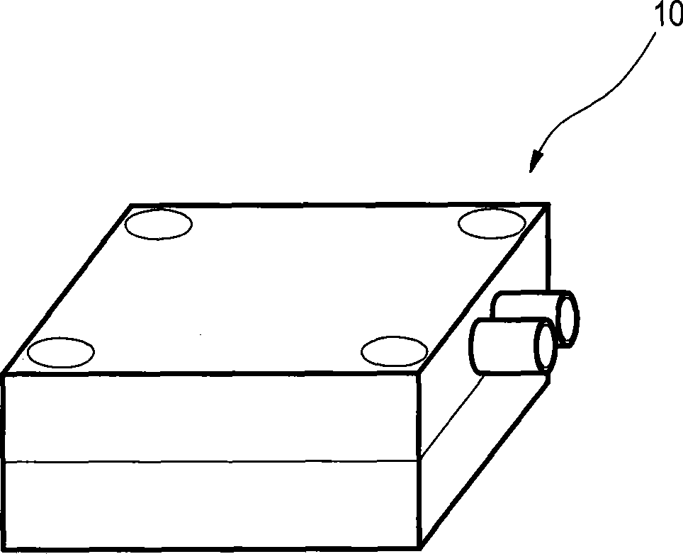
[0039] Please refer to figure 1 , which is a schematic diagram of a flat micropump according to the first embodiment of the present invention. The flat micropump 10 of the first embodiment of the present invention is applied to the delivery of a fluid (not shown in the figure), which can be coolant in a water-cooled heat dissipation system, fuel used in a fuel cell, or blood delivered by an artificial heart Wait.

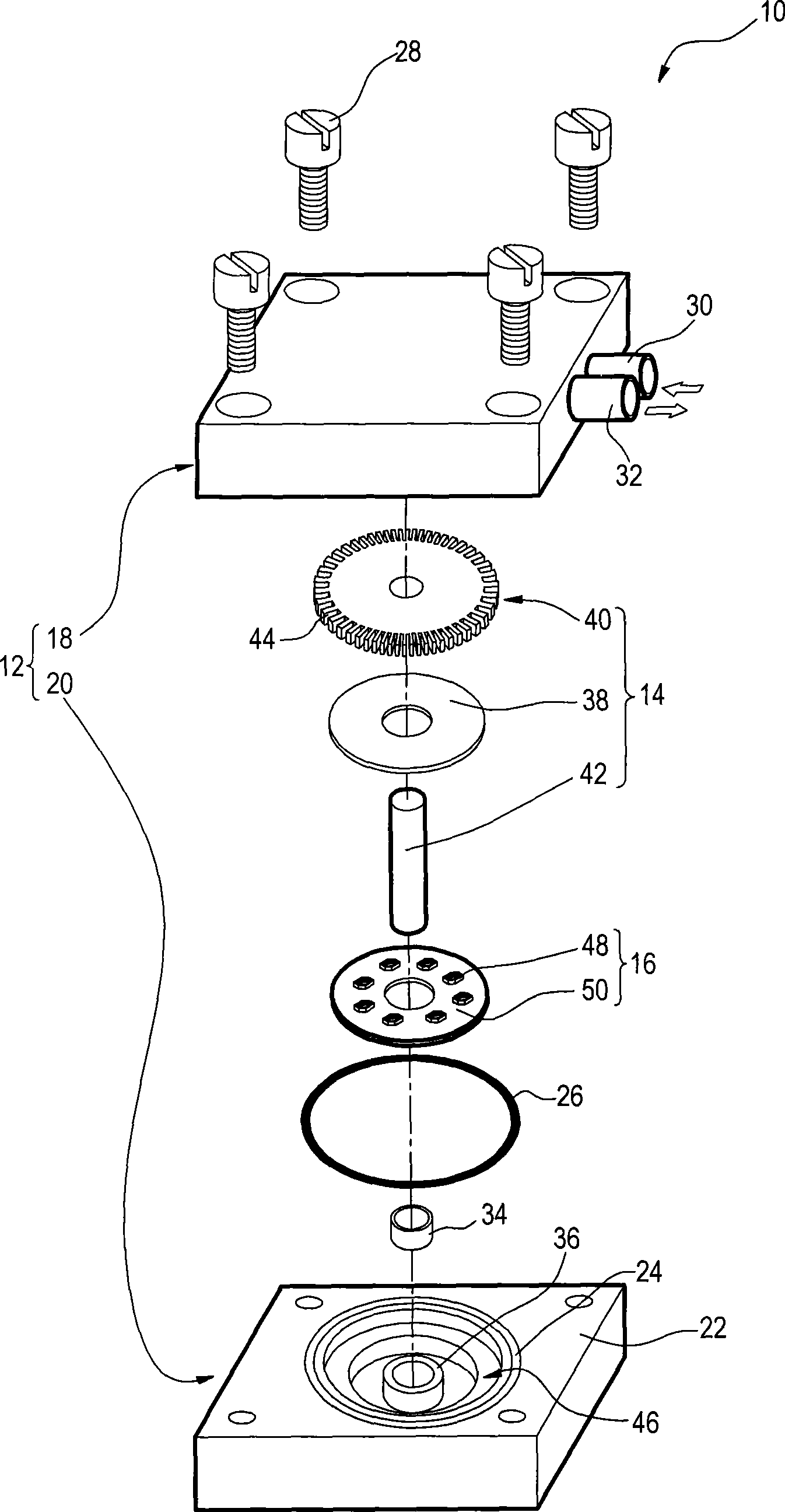
[0040] Please refer to figure 2 , which is a component diagram of the flat micropump according to the first embodiment of the present invention. The flat micropump 10 according to the first embodiment of the present invention mainly includes a main body 12 , a rotor 14 and a stator 16 . The main body 12 includes a cover portion 18 and a bott...


PUM


Abstract

The present invention discloses a flat mini pump which is applied on fluid transporting, the mini pump comprises a main body, a rotor and a stator, wherein the includes a cover and a bottom; a combination surface between the cover and the bottom is provided with a leakage proof apparatus, and the inside of the main body forms a cavity with a inlet and an outlet; the rotor is set inside the cavity and includes a magnet group, a impeller wheel and a axis core, wherein the magnet group is connected on one side of the impeller wheel and rotate coaxially with the impeller wheel through axis core location; the stator is set inside the cavity and include a plurality of coil assemblies in axial direction corresponding to the magnet group, wherein the coil assemblies generate a axial magnetic field with the magnet group to drive the impeller wheel rotate so as to convey the fluid from the inlet to the outlet. The plat mini pump provided in the invention adopts axial magnetic field design, which can minimize volume, enhance rotate torsion force, outlet pressure and heat yield performance of the pump.

Description

technical field [0001] The invention relates to a flat micropump, in particular to a flat micropump designed with an axial magnetic field, which has the advantages of miniaturized volume, high rotational torque, high outlet pressure and good heat dissipation. Background technique [0002] Whether it is used in water-cooled heat dissipation systems, fuel delivery devices in fuel cells, or artificial hearts, micropumps are very important components and play a very critical role. Therefore, designing and manufacturing a micropump with good sealing performance, high rotational torque, high fluid outlet pressure and good motor cooling capacity has become the goal pursued by designers and manufacturers. [0003] The structure of the centrifugal pump generates a magnetic field through the input current of the coil on the stator, and generates a magnetic force with the magnet on the rotor to drive the impeller to rotate and make the fluid flow. According to the motor setting method...

Claims


Application Information

Patent Timeline
Patent Type & Authority Applications(China)
IPC IPC(8): F04D13/06F04D29/22F04D29/046F04D29/08F04D29/42H02K7/14H02K1/14H02K1/27
Inventor 吴信毅黄聪文陈国丰江易儒
Owner METAL INDS RES & DEV CENT
Why Eureka
Try Eureka