Laser cutting method for angle of rotation
A technology of laser cutting and corner turning, which is applied in the direction of laser welding equipment, welding equipment, metal processing equipment, etc., can solve the problems of reduced cutting speed, increased nitrogen consumption, and reduced processing efficiency, so as to reduce impermeable cutting and reduce loss rate , the effect of improving the service life
- Summary
- Abstract
- Description
- Claims
- Application Information
AI Technical Summary
Problems solved by technology
Method used
Image

Examples
Embodiment Construction
[0016] The present invention will be described in further detail below through specific embodiments and in conjunction with the accompanying drawings.
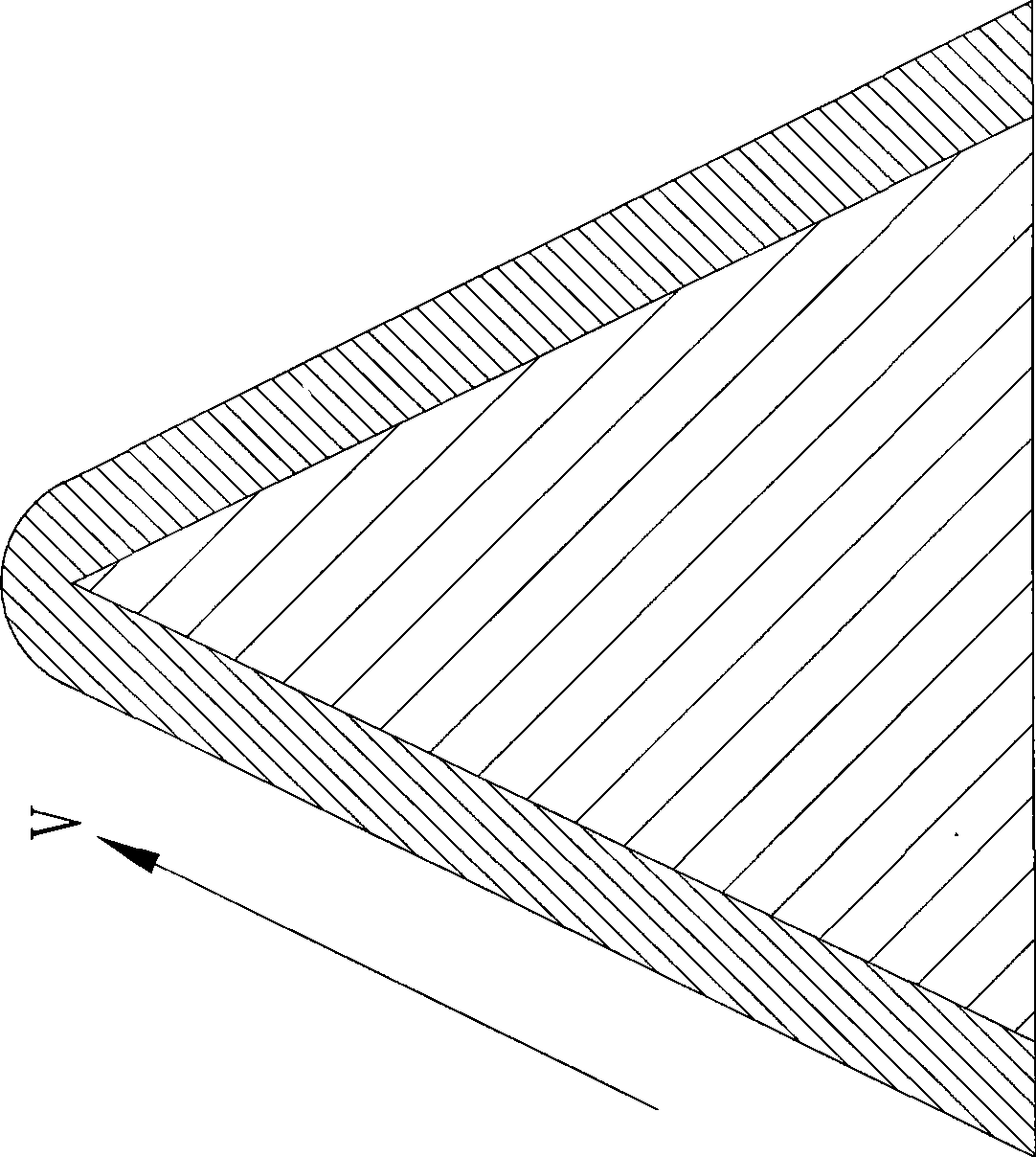
[0017] Such as figure 1 , the present invention is applicable to the laser cutting method of the corner for the laser cutting of thick plate stainless steel material (more than 3MM) of high-power laser cutting machine tool.
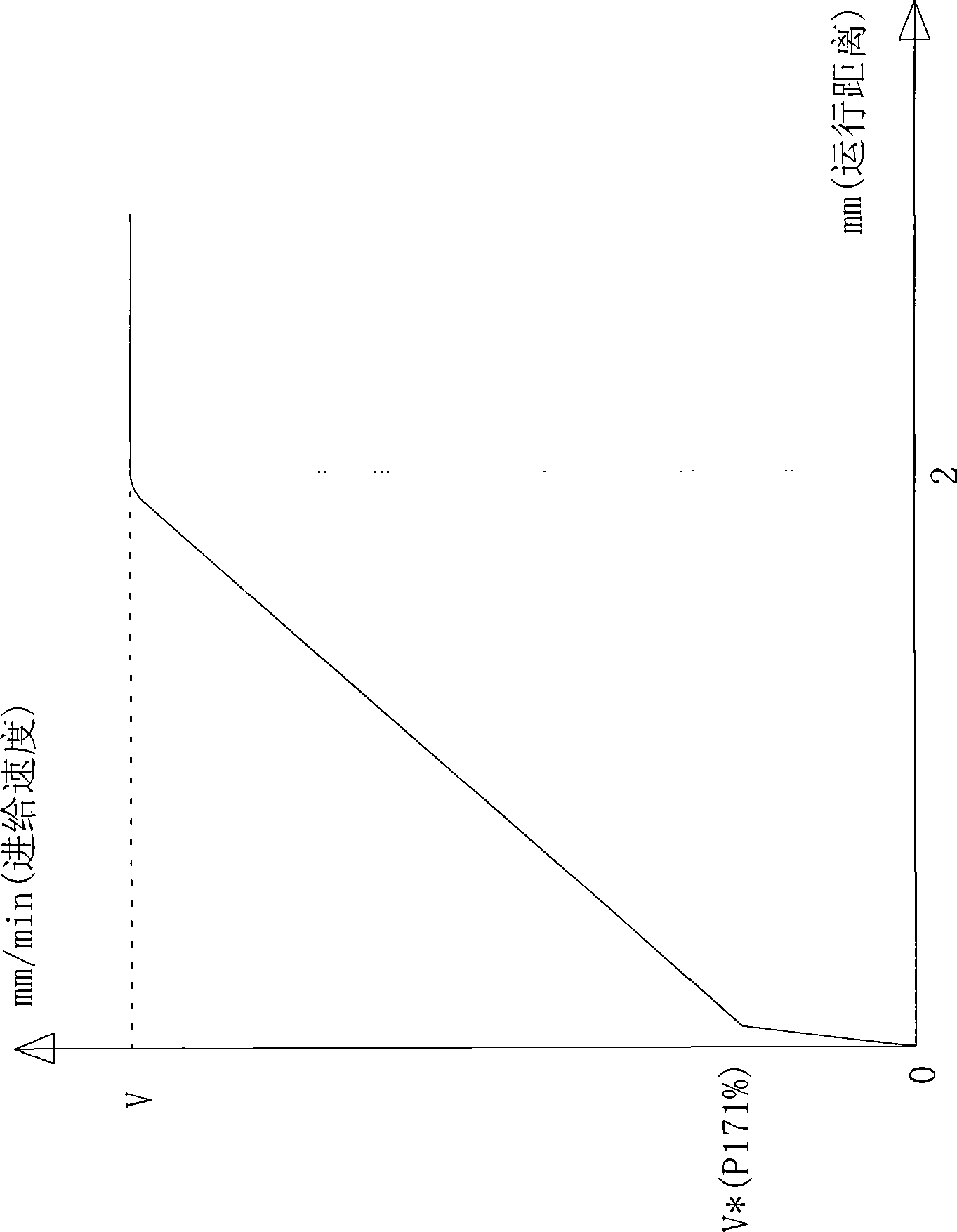
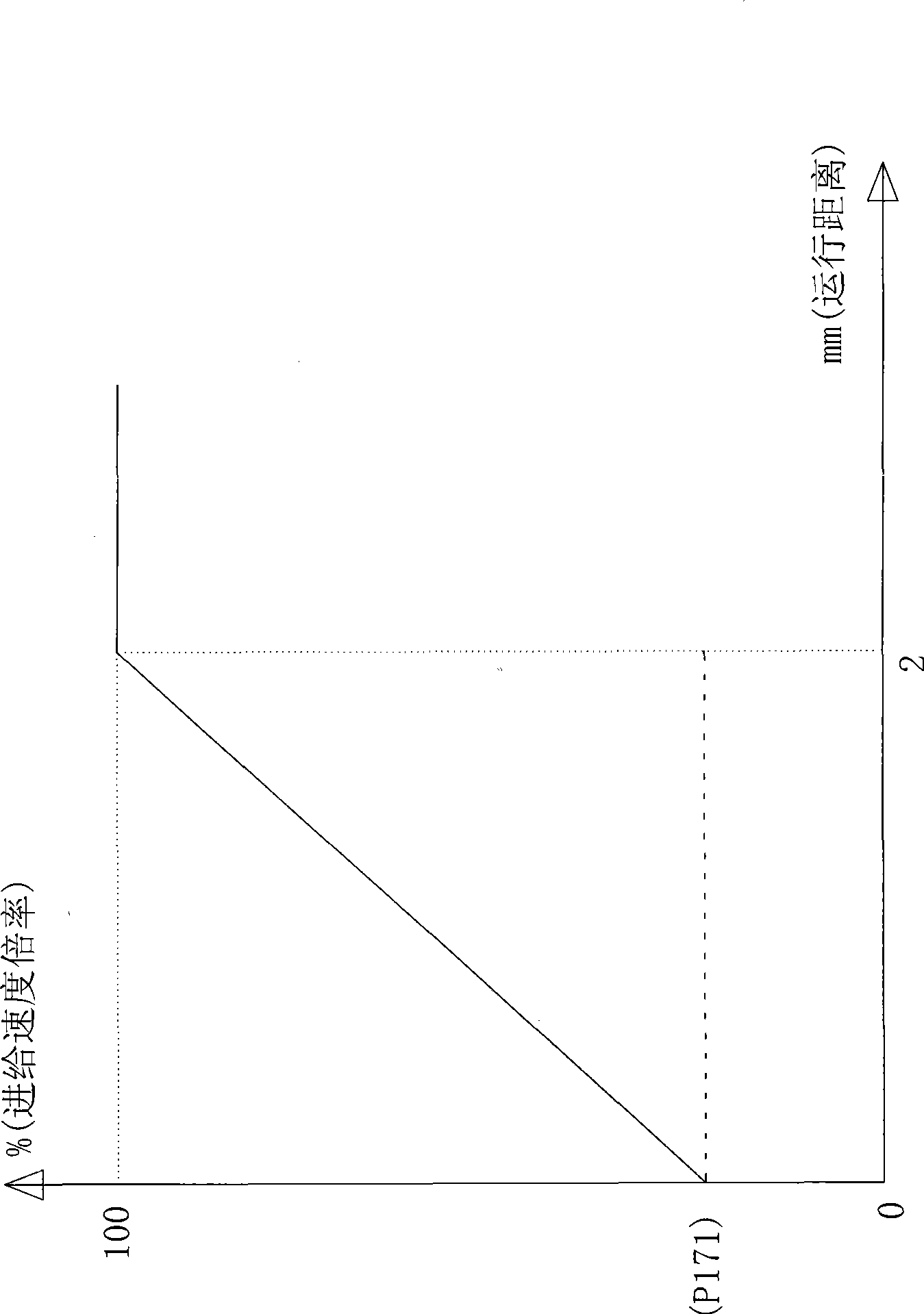
[0018] Such as Figure 2 to Figure 4 , at the corner of the trajectory, the speed multiplier of cutting is controlled as follows (such as Figure 4 ), the steps are as follows:
[0019] a: At the contour corner of the cutting path, the CNC control system judges the contour corner angle according to the shape of the cutting contour;
[0020] b: Set the cutting machine in the motion pause delay state, and preset the value of the minimum speed override parameter P171 at the corner, and write it into the CNC control system through control, so that the speed override of the CNC control system is set at the ...
PUM
 Abstract
Description
Claims
Application Information