
Hydraulic control method and hydraulic control loop for down-hole column clamping device

A technology of control circuit and control method, which is applied to the automatic control system of drilling, oil traps, drilling equipment, etc. It can solve the problems of oil pipes flying out of the wellhead, many workers, and high operating intensity, so as to avoid hidden dangers of accidents and simplify Operation content and the effect of ensuring construction safety

Inactive Publication Date: 2009-07-08
RES INST OF PETROLEUM ENG SHENGLI OIL FIELD SINOPEC
View PDF0 Cites 8 Cited by
  • Summary
  • Abstract
  • Description
  • Claims
  • Application Information

AI Technical Summary

Problems solved by technology

[0004] 1. Once the operator makes a misoperation, the two clamping devices may be in a non-clamping state, causing the tubing to fly out of the wellhead;
[0005] 2. There are many workers on the wellhead platform for pressure operation, and accidentally touching the handle of the reversing valve may cause the tubing to fly out of the wellhead;
[0006] 3. Operators are required to concentrate and operate very carefully, which can easily cause physical and mental fatigue;
[0007] 4. High operating intensity and low efficiency

Method used


Image

  • Hydraulic control method and hydraulic control loop for down-hole column clamping device

Examples


Embodiment Construction

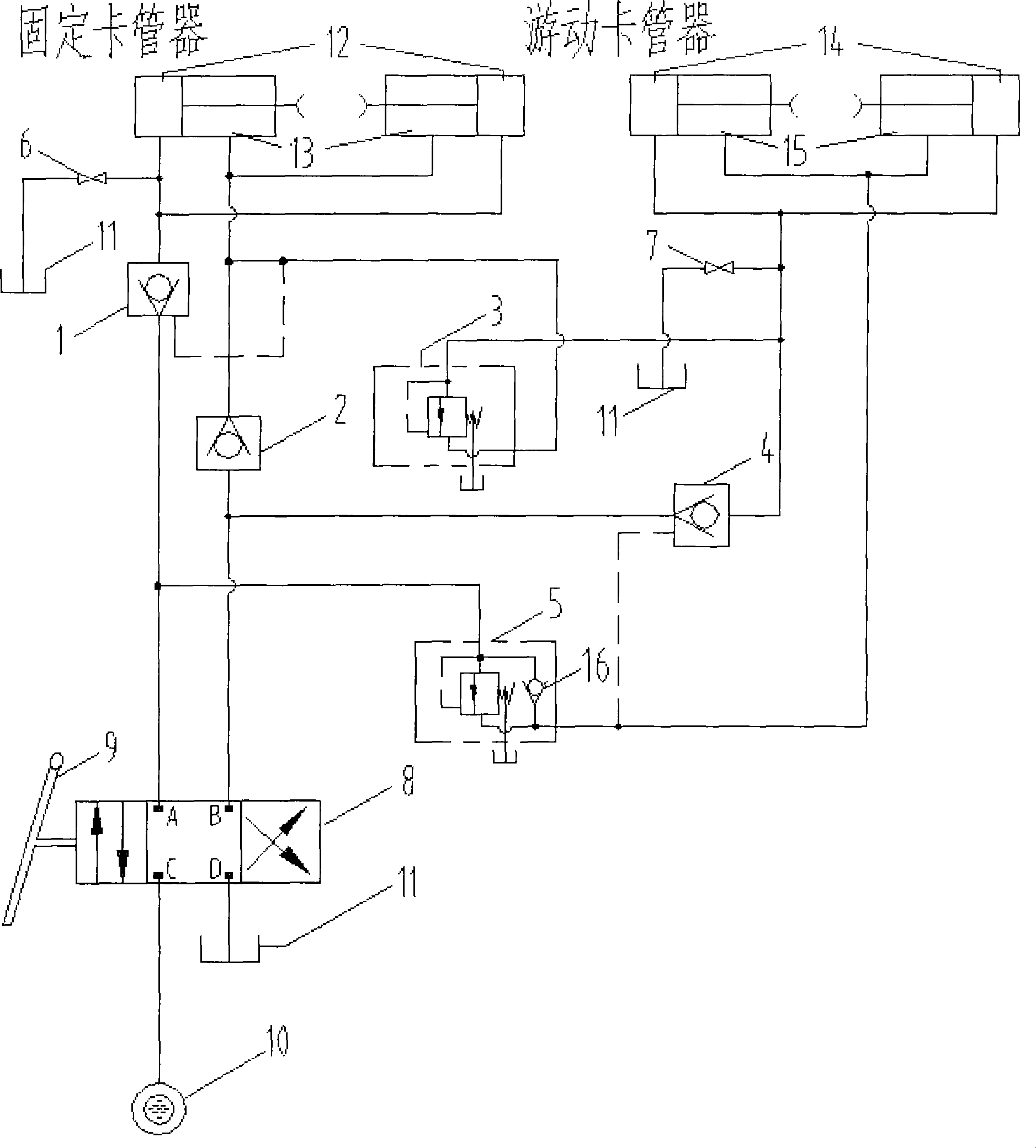
[0014] The present invention will be further described in detail below in conjunction with the accompanying drawings and embodiments: Referring to the accompanying drawings, the hydraulic control method of the downhole pipe string stuck device is to allow the reversing valve 8 to simultaneously control the hydraulic control circuit of the fixed pipe stuck device and the floating pipe stuck device The oil inlet and oil return, so that one of the tube clamps is clamped first, and the other tube clamp can be released, ensuring safe and convenient operation.

[0015] The hydraulic control circuit includes a reversing valve 8, a hydraulic source 10, a large cavity 12 and a small cavity 13 of a fixed tube card cylinder, and a large cavity 14 and a small cavity 15 of a floating tube card cylinder. The large cavity 12 of the fixed tube clamp oil cylinder is connected with the hydraulic control check valve 1, the reversing valve 8 and the hydraulic pressure source 10 through the hydraul...


PUM


Abstract

The invention discloses a hydraulic control method and a hydraulic control loop for a pipe clamping device of an underground pipe column used in the petroleum industry, which is used for operation of an oil-water well under the pressure condition, effectively controls the action of the pipe clamping device, and ensures the safe production. The control method of the invention is to use a reversing valve to simultaneously control the oil inlet and the oil outlet of the hydraulic control loop of a fixed pipe clamping device and a floating pipe clamping device, and ensure that one pipe clamping device is clamped tightly first, and then the other pipe clamping device is loosened. The hydraulic control loop comprises a hydraulic source, a reversing valve, large and small cavities of an oil cylinder of the fixed pipe clamping device and large and small cavities of an oil cylinder of the floating pipe clamping device; the reversing valve and the fixed pipe clamping device and the floating pipe clamping device form a clamping loop and a loosening loop of two pipe clamping devices respectively; a direct control sequence valve is communicated with an oil inlet path of the loosening loop of the fixed pipe clamping device and an oil inlet path of the clamping loop of the floating pipe clamping device; and a direct control unidirectional sequence valve is communicated with an oil inlet path of the clamping loop of the fixed pipe clamping device and an oil inlet path of the loosening loop of the floating pipe clamping device.

Description

technical field [0001] The present invention relates to the downhole operation equipment and the control method of the equipment in the petroleum industry, especially the hydraulic control method and the hydraulic control circuit of the downhole pipe string clamping device. The action of the tube clamp ensures safe production. Background technique [0002] In the workover operation of lifting and lowering tubing in oil and water wells, the snubbing operation is when there is pressure in the well, using a fixed tube clamp and a floating tube clamp to alternately clamp the tubing, and the tubing is pulled out through the loading control device. out or into the well to prevent the tubing from flying out of the wellhead under the pressure in the well. [0003] The fixed tube clamp and the floating tube clamp on the existing pressurized operation device are independently controlled by a three-position four-way reversing valve, but the linkage and interlocking between the two rev...

Claims


Application Information

Patent Timeline
IPC IPC(8): E21B40/00E21B44/00
Inventor 王民轩魏斌高广启罗文莉马珍福任闽燕岳振玉宋辉辉郝丽伟祁新华
Owner RES INST OF PETROLEUM ENG SHENGLI OIL FIELD SINOPEC
Learn More