Expansion ratio adjustable pneumatic engine for automobile and its exhaust pressure control method

A pneumatic engine, exhaust pressure technology, applied to the direction of the one-way flow engine, engine components, variable displacement engine, etc., can solve the problem of low effective energy utilization, to avoid the loss of effective energy of compressed air, reduce compression Air exergy loss, effect of improving energy conversion efficiency

Inactive Publication Date: 2009-07-08
SOUTH CHINA UNIV OF TECH
View PDF0 Cites 30 Cited by
  • Summary
  • Abstract
  • Description
  • Claims
  • Application Information

AI Technical Summary

Problems solved by technology

[0006] In order to overcome the shortage of low effective energy utilization rate of the existing vehicle air engine due to decompression loss and exhaust loss, the present invention provides a vehicle air engine with adj

Method used


Image

  • Expansion ratio adjustable pneumatic engine for automobile and its exhaust pressure control method
  • Expansion ratio adjustable pneumatic engine for automobile and its exhaust pressure control method

Examples


Embodiment Construction

[0027] The present invention will be further described below in conjunction with the accompanying drawings and embodiments.

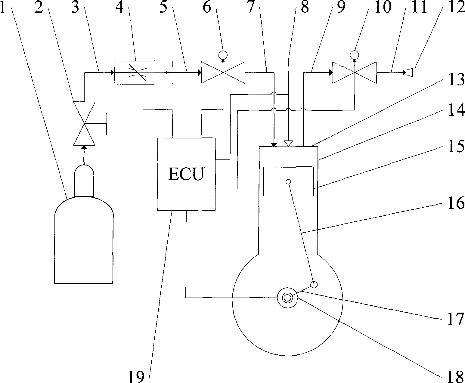
[0028] Such as figure 1 As shown, the vehicle pneumatic engine with adjustable expansion ratio consists of an air storage tank 1, a shut-off valve 2, a high-pressure pipe 3, a flow regulating valve 4, an intermediate pipe 5, an air intake solenoid valve 6, an air intake pipe 7, a cylinder 14, and a cylinder head 13. Piston 15, exhaust pipe 9, exhaust solenoid valve 10, low pressure pipe 11, air outlet 12, pressure sensor 8, connecting rod 16, crankshaft 17, photoelectric encoder 18 and controller 19. The compressed air starts from the air storage tank 1 and passes through the shut-off valve 2, high pressure pipe 3, flow regulating valve 4, intermediate pipe 5, intake solenoid valve 6, intake pipe 7, cylinder 14, exhaust pipe 9, exhaust solenoid valve 10. Low-pressure pipe 11, air outlet 12, and finally discharged into the atmosphere. The high-pressure...


PUM


Abstract

The invention relates to a pneumatic engine for car use and discloses a pneumatic engine for car use with an adjustable expansion ratio and an exhaust pressure control method. According to the pneumatic engine for car use with the adjustable expansion ratio, compressed air is expanded in a cylinder so as to propel a piston and drive a crankshaft to rotate through a connecting rod and output rotating mechanical work to the outside. The pneumatic engine is characterized in that the pneumatic engine comprises an air inlet electromagnetic valve which is arranged in a cylinder air inlet pipe, an exhaust electromagnetic valve which is arranged in a cylinder exhaust pipe, a pressure sensor which is used for detecting the air pressure inside the cylinder, a photoelectric encoder which is used for detecting a crankshaft rotation angle, and a controller; and the controller makes a policy according to the cylinder air pressure detected by the pressure sensor and the crankshaft rotation angle of the photoelectric encoder, and sends a control signal of opening or closing to the air inlet electromagnetic valve and the exhaust electromagnetic valve. The pneumatic engine reduces the compressed air available energy loss caused by high pressure exhaust, thereby improving the energy conversion rate of the pneumatic engine.

Description

technical field [0001] The invention relates to a vehicle pneumatic engine, in particular to a vehicle pneumatic engine with an adjustable expansion ratio and a method for controlling the exhaust pressure thereof. Background technique [0002] The pneumatic engine is an important component of the power system of a zero-pollution, environment-friendly and energy-saving vehicle. Its function is to convert the effective energy of compressed air into the rotational mechanical energy required to drive the vehicle. [0003] Existing pneumatic motors for vehicles generally consist of parts such as a motor body, a pressure reducing valve, a flow regulating valve, an air storage tank and an air pipeline. The compressed air is stored in the air storage tank. When the air motor is working, the compressed air flows through the air pipeline, pressure reducing valve, flow regulating valve, air inlet, cylinder and exhaust port, and finally is discharged into the atmosphere. The pressure r...

Claims


Application Information

Patent Timeline
IPC IPC(8): F01B17/02F01B25/02
Inventor 谢小鹏徐正冈陈树林
Owner SOUTH CHINA UNIV OF TECH
Why Eureka
Try Eureka