Security induction valve and security buffering two-purpose valve employing the same

A safety and valve body technology, applied in the direction of machines/engines, etc., can solve the problems of insensitive safety valve response, inability to effectively relieve pressure, and high cost, and achieve the effects of simple structure, extended service life, and reliable operation

Active Publication Date: 2009-07-08
曹康年
View PDF0 Cites 2 Cited by
  • Summary
  • Abstract
  • Description
  • Claims
  • Application Information

AI Technical Summary

Problems solved by technology

Some use auto-transformation to start or set delay elements in the electric control cabinet, which is expensive, and there is still a certain impact when the voltage changes
In addition, most of the safety valves set up for safe operation are not very sensitive, and can only serve as a little warning when overpressure occurs, and cannot effectively relieve pressure.

Method used


Image

  • Security induction valve and security buffering two-purpose valve employing the same
  • Security induction valve and security buffering two-purpose valve employing the same
  • Security induction valve and security buffering two-purpose valve employing the same

Examples


Embodiment 1

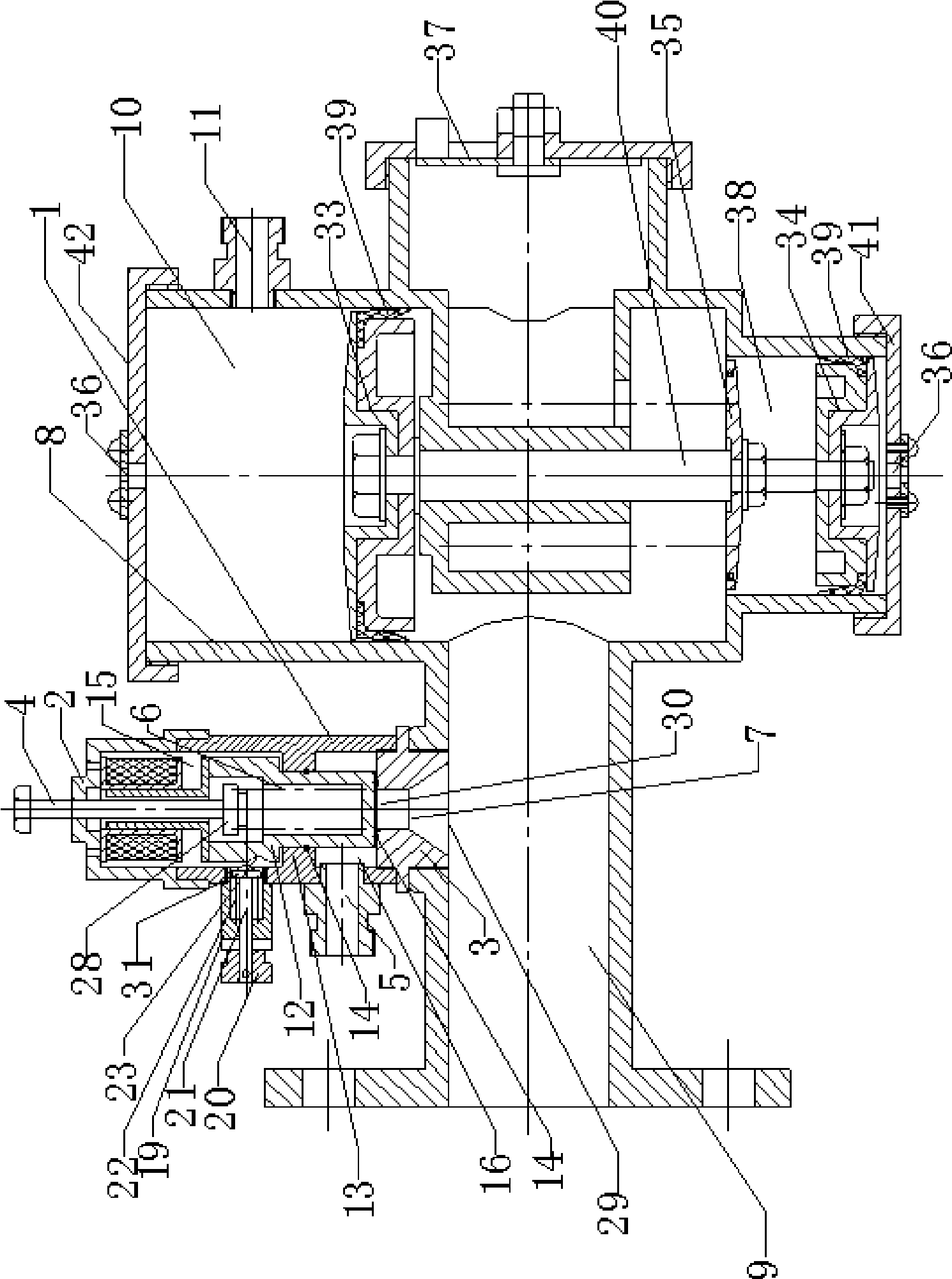
[0042] Such as figure 1 and 2 As shown, the safety buffer dual-purpose valve of the present invention includes a safety buffer dual-purpose valve body 8, a safety induction valve, a large piston 33, a small piston 34, an opening and closing valve plate 35, a damping hole 36, and an initial pressure regulating valve plate 37 And the upper valve cover 42, the safety induction valve is located at the entrance of the valve body 1 pipeline 9, the large piston 33, the small piston 34, and the opening and closing valve plate 35 in the valve body 1 are connected and fixed by the connecting shaft 40, and the large piston 33 connects the valve body 1 is divided into an upper air chamber 10 and a lower air chamber 38. The pipe joint 11 on one side of the upper air chamber 10 communicates with the joint head 5 of the safety induction valve through a pipe. The bonnet 42 is fixed on the upper part of the valve body 1, the upper bonnet 42 is provided with a damping hole 36 in the center, th...

Embodiment 2

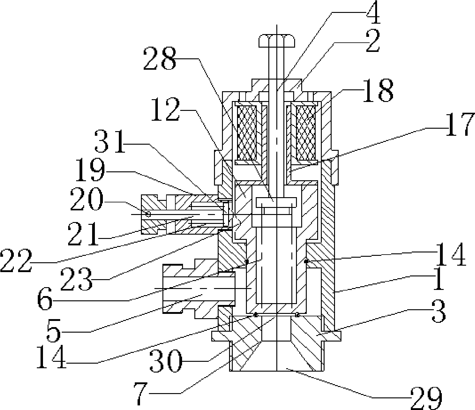
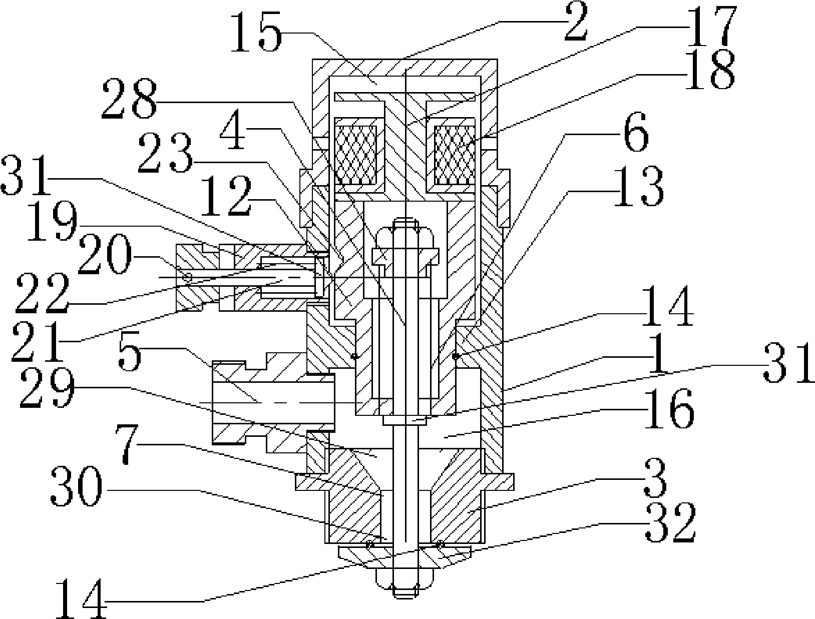
[0044] Such as image 3 and 4 As shown, the electromagnetic valve coil 18 and the electromagnet 17 of the safety induction valve in the vacuum state are fixed on the upper end surface of the valve core 12, and there is a gap between the electromagnetic valve coil 18 and the upper end of the electromagnet 17, and the pressure adjustment mechanism of the safety induction valve includes adjustment bolts 4 , spring 6, spring seat 28, snap ring 31 and valve plate 32, one end of adjusting bolt 4 sleeved with spring 6 is provided with spring seat 28, spring 6 is fixed between spring seat 28 and the bottom of spool 12, adjusting bolt 4 Passing through the bottom of the valve core 12 and the valve seat port 7, the snap ring 31 of the adjusting bolt 4 is located in the lower cavity 16, and the other end of the adjusting bolt 4 is fixed with a valve plate 32. Valve seat 3 is provided with valve seat port 7, and valve seat port 7 is made up of large port 29 and small port 30, and the end...

Embodiment 3

[0046] Such as Figure 5 , 6 , 7 and 8, a manual unloading mechanism is provided on the side wall of the valve body 1 corresponding to the safety induction valve locking device, and the manual unloading mechanism includes an unloading lever 25 and a base 26 with a handle 24, and The spool 12 on the corresponding side of the base 26 is provided with an unloading hole 27, and the axial width of the unloading hole 27 is equal to the up and down travel distance of the spool 12. Other structures of the safety induction valve and the structure of the dual-purpose safety buffer valve are the same as those in Embodiment 1, 2.


PUM


Abstract

The invention relates to a safe induction valve. A valve core is arranged in a valve body; an annular sealing ring is arranged between the middle part of the valve core and an inner convex ring of the valve body; the annular sealing ring divides the valve body into an upper cavity and a lower cavity; one side of the middle part of the valve body is provided with a locking device; an electromagnetic valve is arranged in the valve body on the upper part of the valve core; and a pressure adjusting mechanism is also arranged in the valve body. The invention also relates to a safe buffer double-purpose valve applying the safe induction valve with the structure, wherein the center of an upper valve cap is provided with a damping hole, the lower end of the valve body is provided with a lower valve cap, and the center of the lower valve cap is provided with a damping hole. The combined application of the induction valve and the safe buffer double-purpose valve can replace an atmospheric valve, a safety valve and an electric unloading valve simultaneously. The induction valve and the safe buffer double-purpose valve have the advantages of simple structure, reliable running, convenient use, wide application and low price.

Description

technical field [0001] The invention relates to a safety induction valve. [0002] The present invention also relates to a safety buffer dual-purpose valve using the safety induction valve with the above-mentioned structure. Background technique [0003] At present, some fluid compression machinery such as Roots blowers are required to start without load and no load, and then gradually load until full load. When stopping, unload first and then shut down the motor. When the system is overloaded, there must be a safety protection device. For this reason, in the past It is to install a manual vent valve on the system bypass, gradually open or close the vent valve when starting or stopping to achieve the above purpose, but the reality is that most users do not operate according to the regulations, but start or stop directly, causing the fan The strong impact when the motor starts and stops seriously affects the service life of the unit, especially for large-capacity motors, the...

Claims


Application Information

Patent Timeline
Patent Type & Authority Applications(China)
IPC IPC(8): F04C28/28
Inventor 曹康年
Owner 曹康年
Why Eureka
Try Eureka