Configurable frequency synthesizer circuit based on time-delay lock loop

A delay-locked loop and frequency synthesis technology, which is applied in the direction of electrical components and power automatic control, can solve the problems that the delay-locked loop frequency synthesis circuit cannot be used, and the user is not easy to change the frequency synthesis coefficient flexibly, so as to improve the jitter performance, Excellent anti-jitter performance, avoiding the effect of output errors

Active Publication Date: 2009-07-08
BEIJING MXTRONICS CORP +1
View PDF0 Cites 46 Cited by
  • Summary
  • Abstract
  • Description
  • Claims
  • Application Information

AI Technical Summary

Problems solved by technology

[0005] The problem that the previous research has not solved is: the delay-locked loop frequency synthesis circuit cannot use the principle of the phase-locked loop frequency synthesis-add a programmable frequency divider to the feedback l

Method used


Image

  • Configurable frequency synthesizer circuit based on time-delay lock loop
  • Configurable frequency synthesizer circuit based on time-delay lock loop
  • Configurable frequency synthesizer circuit based on time-delay lock loop

Examples


Embodiment Construction

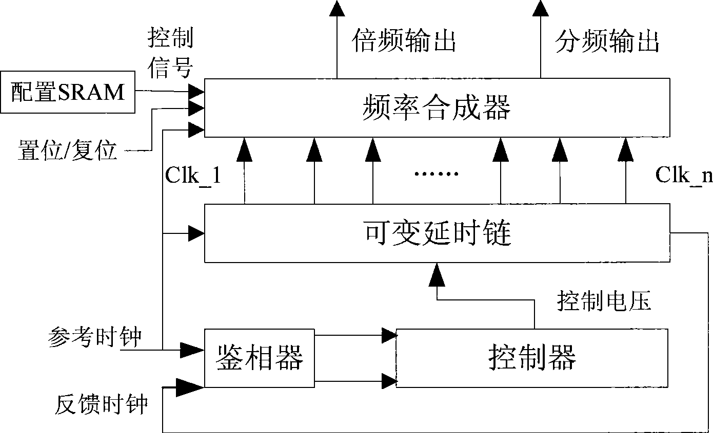
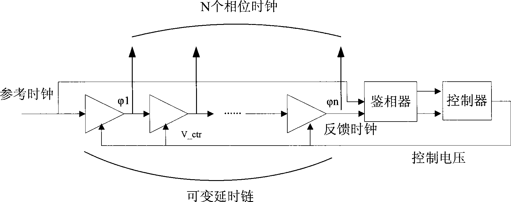
[0027] Such as figure 1 As shown, the configurable delay-locked loop frequency synthesis circuit of the present invention includes a delay-locked loop composed of a phase detector, a controller and a variable delay chain, a frequency synthesizer composed of a frequency multiplication synthesizer and a frequency division synthesizer , configure SRAM. The phase detector receives the reference clock and the feedback clock, and outputs the comparison signal and the lock signal after phase discrimination and comparison. After the comparison signal and the lock signal are processed by the controller, they output the control voltage to control the variable delay chain to generate N phase clocks and output them to the frequency synthesis device. The frequency synthesizer processes N phase clocks, under the control of the configuration SRAM, by selecting the appropriate phase clock to control the set / reset time of the RS flip-flop in the frequency multiplication synthesizer and freque...


PUM


Abstract

The invention relates to a configurable frequency synthesis circuit based on a delay locked loop. The circuit comprises the delay locked loop, a frequency synthesizer and a configuring SRAM, wherein, the delay locked loop consists of a phase discriminator, a controller and a variable delay chain; and the frequency synthesizer consists of a frequency doubling synthesizer and a frequency division synthesizer. The phase discriminator receives a reference clock and a feedback clock and outputs comparison signals and locking signals after phase demodulation comparison; the comparison signals and the locking signals are processed by the controller, and the controller outputs control voltage then in order to enable the variable delay chain to generate N phase clocks that are output to the frequency synthesizer; and the frequency doubling synthesizer and the frequency division synthesizer enable the set/reset time of a R/S trigger in the frequency doubling synthesizer to generate frequency doubling clock signals under the control of the configuring SRAM, and lead the set/reset time of the R/S trigger in the frequency division synthesizer to generate frequency division clock signals. The configurable frequency synthesis circuit has simple circuit organization, flexibly changes a frequency synthesis coefficient by changing the code flow value in the embedded configuring SRAM so as to obtain a frequency division coefficient and a frequency doubling coefficient as required, and can be applied to a field programmable logic array.

Description

technical field [0001] The present invention relates to a frequency synthesis circuit, in particular to a configurable frequency synthesis circuit based on a delay-locked loop, which is mainly used in a field programmable logic array (FPGA), and can be configured into various working modes according to user requirements , to achieve different frequency division and multiplication requirements. Background technique [0002] With the continuous development of large-scale and high-integration integrated circuits, the quality of clocks in integrated circuits is becoming more and more important, especially the requirements for the stability and accuracy of clocks are getting higher and higher. In modern electronic technology, crystal oscillators are generally used to obtain high-precision and high-stability clocks. However, because the clock frequency it generates is single, it can only be fine-tuned in a very small range. In order to generate a variety of other frequency clock ...

Claims


Application Information

Patent Timeline
IPC IPC(8): H03L7/18
Inventor 王慜文治平陈雷张彦龙张志权
Owner BEIJING MXTRONICS CORP
Why Eureka
Try Eureka