Rapid thermal firing ir conveyor furnace having high intensity heating section

A heat treatment furnace and conveyor belt technology, applied in the field of metallization and sintering, can solve the problems affecting the heat distribution curve, lamp vibration, fatigue failure output, etc., and achieve the effects of increasing production volume, increasing production capacity, and increasing speed.

Inactive Publication Date: 2009-07-08
TP SOLAR OF USA
View PDF0 Cites 26 Cited by
  • Summary
  • Abstract
  • Description
  • Claims
  • Application Information

AI Technical Summary

Problems solved by technology

[0017] (4) Regulating phase (such as melting), which is a small amount of additives proprietary to the slurry manufacturer, but used in sintering affects the required

Method used


Image

  • Rapid thermal firing ir conveyor furnace having high intensity heating section
  • Rapid thermal firing ir conveyor furnace having high intensity heating section
  • Rapid thermal firing ir conveyor furnace having high intensity heating section

Examples


Embodiment Construction

[0064] The following detailed description sets forth the present invention by way of example, rather than limiting the scope, equivalents or principles of the present invention. This description clearly enables one of ordinary skill in the art to understand and use the invention, and describes several embodiments, modifications, variations, substitutions and uses of the invention, including what is presently believed to be the best mode of carrying out the invention.

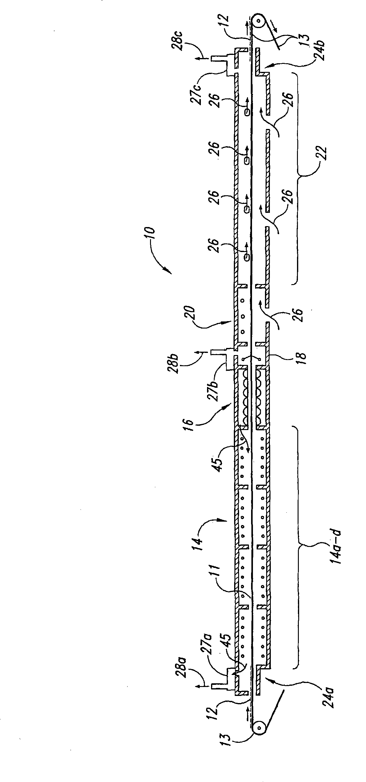
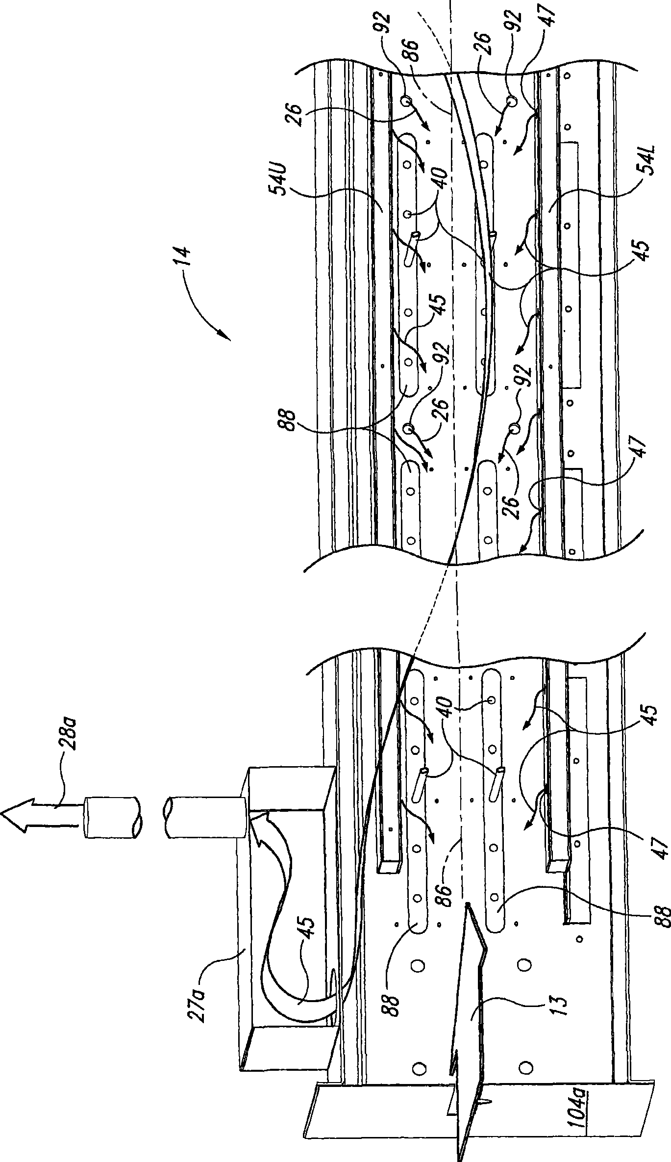
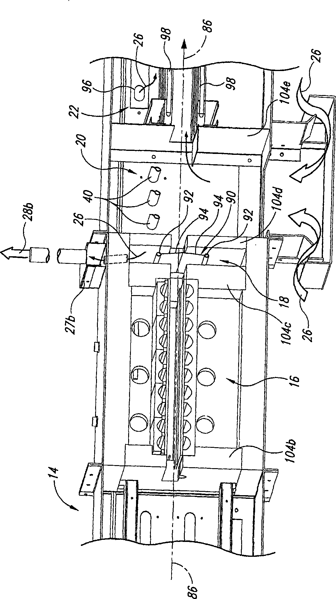
[0065] In this regard, the invention has been illustrated in multiple figures and is of sufficient complexity that the many components, interrelationships, and subcombinations thereof cannot be fully illustrated in only a single patent type figure. For purposes of clarity and conciseness, the various figures are shown schematically or with the omission of components that are not essential to describing the specific structures, aspects or principles of the disclosed inventions. For example, the various electrical...


PUM


Abstract

Isolation IR heat lamp module and method of firing multi-zone IR furnaces for solar cell processing comprising lamps disposed in individual parallel channels in a reflector/insulator body to provide a cooling air channel surrounding each tube; the channels are covered with IR-transmissive plate material to isolate each lamp from adjacent lamps and the process zone. Cooling air is exhausted and recycled upstream for energy conservation. Lamp spacing can be varied and power to each lamp individually controlled to provide infinite control of temperature profile in each heating zone. For a spike zone, and in combination with downstream quench control and annealing zones, steep heating and cooling curves with very short dwell (sharp) peak temperature profiles permit faster throughput due to operation of the lamps at essentially 100 % rated capacity, at a 2X or greater heating and throughput rate without compromising lamp life, while producing solar cells with improved output efficiency.

Description

technical field [0001] This application relates to an improved IR (infrared) conveyor belt heat treatment furnace, especially for screen printing, metallization sintering of silicon wafers for solar cells, which has an improved peak zone and sintering process, so that the produced Photovoltaic components for solar cells have higher production capacity and efficiency. This improved system is characterized by the use of a specially constructed high reflectance-efficiency reflector in conjunction with an IR heating lamp element spaced from the reflector to form a cooling channel in the peak region heating chamber, which The cooling channels allow the available power density of the heat treatment furnace to be increased sufficiently that the infrared lamps can be operated at up to 100% of their rated power output for extended periods of time without overheating. The system of the present invention also concentrates the infrared light generated by the lamps so that a greater amoun...

Claims


Application Information

Patent Timeline
IPC IPC(8): A21B2/00F26B3/30A45D20/40
CPCY02E10/52
Inventor R·W·帕克斯P·G·雷葛L·A·R·卡西亚R·G·克鲁杰克
Owner TP SOLAR OF USA
Why Eureka
Try Eureka