Control method and control device for hydraulic shovel scraper bucket

A technology for hydraulic excavators and control methods, applied to mechanically driven excavators/dredgers, etc., can solve the problems that the ditch bottom or the level of the site cannot meet the construction requirements, affect the construction quality, and are not accurate enough to achieve simplification Difficulty of operation, saving input cost, and high precision

Inactive Publication Date: 2009-07-15
SANY HEAVY MACHINERY
View PDF0 Cites 34 Cited by
  • Summary
  • Abstract
  • Description
  • Claims
  • Application Information

AI Technical Summary

Problems solved by technology

[0005] As mentioned above, since the control of the three parts of the boom, arm and bucket requires manual control of each hydraulic lever, the combined action of the three completes the control of the bucket operation, and the operation is complicated. It is in...

Method used


Image

  • Control method and control device for hydraulic shovel scraper bucket

Examples


Embodiment 1

[0031] Embodiment one: a kind of control method of hydraulic excavator bucket movement, comprises the following steps:

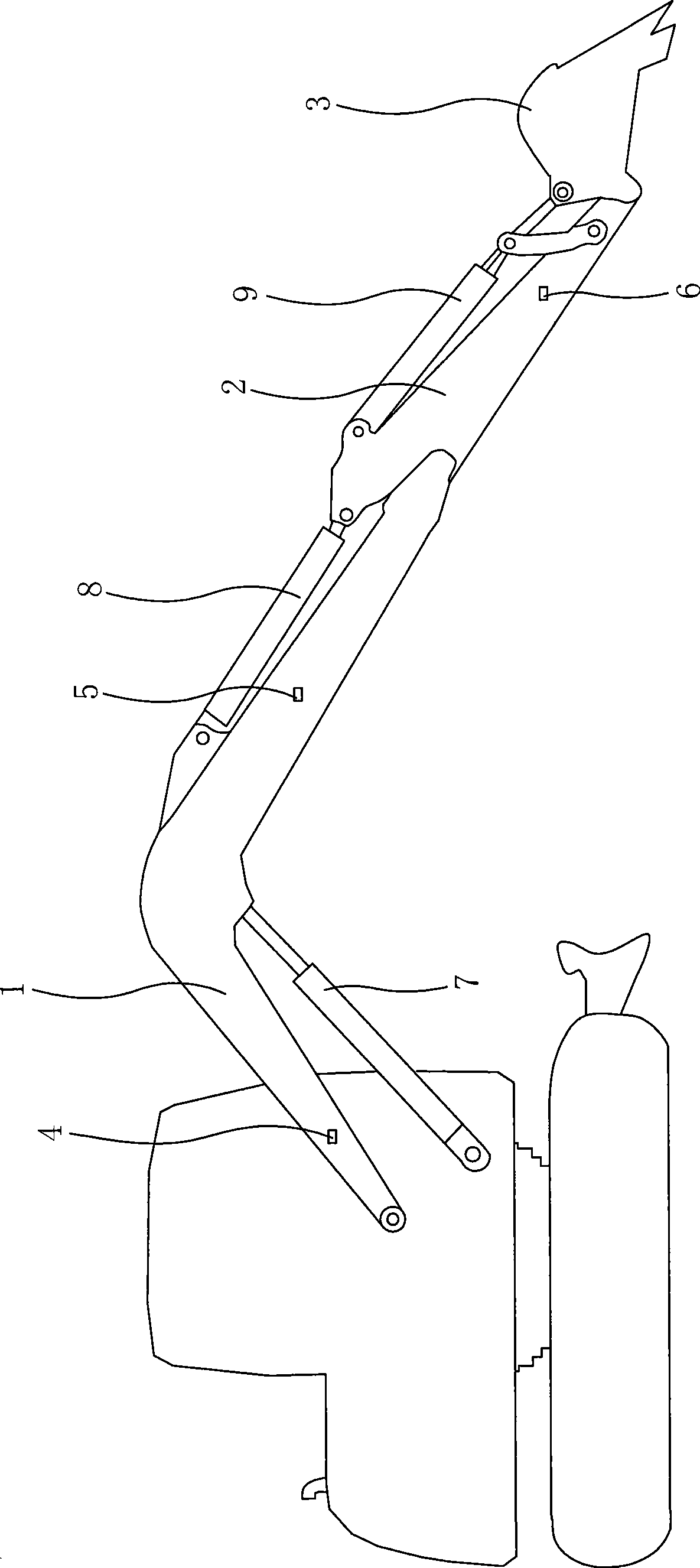
[0032] (1) The hinge angle value between the boom 1, arm 2 and bucket 3 of the current working device is measured by the sensor;

[0033] (2) input the included angle value obtained in the step (1) into a programmable controller with a program, and calculate the moving distance value of each working device required to keep the bucket moving horizontally;

[0034] (3) According to the moving distance value calculated in step (2), the oil supply quantity of the oil cylinder controlling the moving distance of each working device is converted, and delivered to each working device;

[0035] (4) Repeat step (1) until the horizontal operation is completed.

[0036] see figure 1 As shown, in order to realize the above control method, the control device includes an angle sensor, a programmable controller with a software program, and a proportional valve for control...

Embodiment 2

[0038] Embodiment two: a kind of control method of hydraulic excavator bucket motion, comprises the following steps:

[0039] (1) The length signal value of the piston rod of the oil cylinder on each part of the boom 1, arm 2 and bucket 3 of the current working device is measured by the sensor;

[0040] (2) input the length signal value obtained in the step (1) into a programmable controller with a program, and calculate the required oil cylinder piston rod length change value to keep the bucket moving horizontally;

[0041](3) According to the change value calculated in step (2), the oil supply quantity of the oil cylinder controlling the moving distance of each working device is converted, and delivered to each working device;

[0042] (4) Repeat step (1) until the horizontal operation is completed.

[0043] In order to realize the above-mentioned control method, the control device includes a length sensor, a programmable controller with a software program, and a proportion...


PUM


Abstract

The invention discloses a method for controlling the movement of a scraper bucket of a hydraulic excavator, comprising the steps: (1) the included angle value of each part of a working device or the length value of a piston rod is measured by a transducer; (2) the value is input into a programmable controller, and each displacement distance value of the working device, which is required to keep the horizontal displacement of the scraper bucket is obtained through calculation; (3) the oil supply amount of each oil cylinder is obtained through conversion and then is transmitted to each working device; and (4) the step (1) is repeated until the operation is accomplished. Devices for the method comprise angular transducers, a programmable controller with a software program and proportional valves controlling the oil volume of oil cylinders of each working device, wherein the signal output end of each transducer is connected with the programmable controller with the software program, and the output end of the controller is connected with each proportional valve controlling the oil volume. The method has the technical scheme that angular or length signals are obtained through measurement by each transducer, and oil is quantificationally supplied to the oil cylinders by the calculation of the controller, thereby realizing the horizontal movement of the scraper bucket, simplifying the operation and improving the accuracy of the leveling operation.

Description

technical field [0001] The invention relates to a hydraulic excavator, in particular to a method and a control device for controlling the movement of a bucket of the hydraulic excavator. Background technique [0002] The main purpose of an excavator is to extract material from the earth's surface and transfer it to the discharge point, then transfer it back to the excavation site, and repeat. At present, the widely used excavator is hydraulic excavator, which has the advantages of flexible construction and high efficiency, so it is widely used in foundation excavation of housing construction and cleaning after completion, urban pipeline laying, farmland water conservancy construction and other occasions. [0003] A hydraulic excavator is generally composed of several parts such as a working device, a slewing device, a traveling device and a hydraulic control device. The body and the working device are transferred to the slewing device, and the slewing device is fixed on the...

Claims


Application Information

Patent Timeline
IPC IPC(8): E02F3/43
Inventor 戴晴华胡奇王会华
Owner SANY HEAVY MACHINERY
Why Eureka
Try Eureka